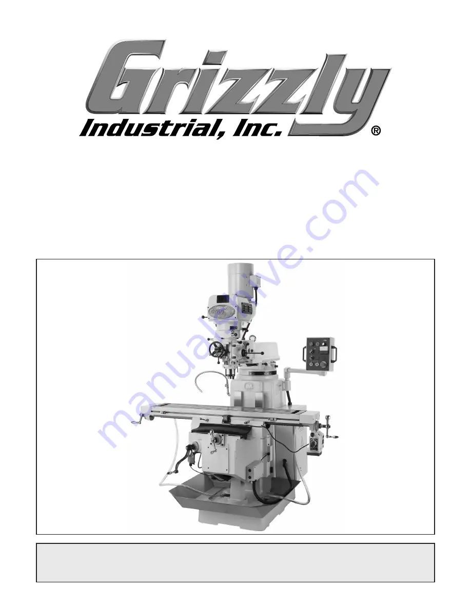
Grizzly G0669X Скачать руководство пользователя страница 1

MODEL G0669X

HIGH-PRECISION 10" X 54"

VS MILLING MACHINE

OWNER'S MANuAL

Copyright © JULy, 2008 By grizzLy indUstriaL, inC.

WARNING: NO PORtION Of tHIS MANuAL MAy bE REPRODuCED IN ANy SHAPE

 OR fORM WItHOut tHE WRIttEN APPROVAL Of GRIzzLy INDuStRIAL, INC.

 #ts10556  printed in taiWan

Содержание G0669X

Страница 1: ...4 VS MILLING MACHINE OWNER S ManuaL Copyright JULY 2008 By Grizzly Industrial Inc Warning No portion of this manual may be reproduced in any shape Or form without the written approval of Grizzly Industrial inc TS10556 printed IN TAIWAN ...

Страница 2: ...PERSONAL PROTECTIVE EQUIPMENT 4HE MANUFACTURER WILL NOT BE HELD LIABLE FOR INJURY OR PROPERTY DAMAGE FROM NEGLIGENCE IMPROPER TRAINING MACHINE MODIFICATIONS OR MISUSE 3OME DUST CREATED BY POWER SANDING SAWING GRINDING DRILLING AND OTHER CONSTRUCTION ACTIVITIES CONTAINS CHEMICALS KNOWN TO THE 3TATE OF ALIFORNIA TO CAUSE CANCER BIRTH DEFECTS OR OTHER REPRODUCTIVE HARM 3OME EXAMPLES OF THESE CHEMICAL...

Страница 3: ...One Shot Oiler 67 Control Panel Electrical Components 67 Electrical Cabinet 68 Accessories 69 Label Placement 70 WARRANTY AND RETURNS 73 INTRODUCTION 2 Foreword 2 Contact Info 2 Functional Overview 2 Identification 3 Machine Data Sheet 6 SECTION 1 SAFETY 9 Safety Instructions for Machinery 9 Additional Safety Instructions For Mills 11 SECTION 2 CIRCUIT REQUIREMENTS 12 220V Single Phase Operation 1...

Страница 4: ...A 98227 2069 Email manuals grizzly com Contact Info Functional Overview The Model G0669X vertical mill is used to remove material from metal workpieces to form complex shapes Tooling is inserted into the spindle of the head which can positioned in nearly any configu ration above the table and workpiece During most operations the tooling rotates in a stationary position while the operator moves the...

Страница 5: ...rive System F Emergency Spindle Brake G Quill Speed Selector H Quill I Spindle J Table K Longitudinal X Axis Ball Handle L Vertical Knee or Z Axis Crank M Vertical Crank Safety Switch N One Shot Lubricator O Vertical Power Feed Motor 1 10 HP 110V P Coolant Return Hose Q Machine Mounting Point 1 of 4 R Knee Locks S Coolant Pump Access in Column T Column U Coolant Valve and Nozzle G P Q R S T U ...

Страница 6: ...l Auto Downfeed Selector C Control Panel see Page 24 for more detail D Longitudinal Power Feed Limit Switch E Table Lock F Longitudinal Ball Handle G Longitudinal Power Feed H Longitudinal Power Feed Limit Stop I Front Way Cover J Splash Pan K Vertical Crank L Cross Feed Y Axis Ball Handle M Saddle N Rear Way Cover O Coolant Nozzle D F G H I J L K O N ...

Страница 7: ... Controls D Main Power Switch on back of Electrical Cabinet E Electrical Cabinet F Auxiliary 110V Outlets on back of Electrical Cabinet G Power Cord H Vertical Power Feed Limit Switch I Longitudinal Power Feed J Ram Forward Backward Tilt Controls K Coarse Downfeed Handle L Quill Auto Downfeed Selector M Spindle Speed Range Selector A B C D E F G H I K L M J ...

Страница 8: ... Yi Z i m m Electrical EdlZg GZfj gZbZci K H c aZ E VhZ Hl iX DC D EdlZg Hl iX ckZgiZg IneZ NVhV VlV K 6I E ckZgiZg H oZ E GZXdbbZcYZY 8 gXj i H oZ 6 GZXdbbZcYZY Eaj GZXZeiVXaZ C B6 A Motors Spindle Motor IneZ I 8 cYjXi dc dghZedlZg E KdaiV Z K E VhZ E VhZ 6beh 6 HeZZY GEB 8nXaZ o EdlZg IgVch Zg 7Zai 9g kZ 7ZVg c h H ZaYZY AjWg XViZY Coolant Pump Motor IneZ cYjXi dc dghZedlZg E KdaiV Z K E VhZ H c...

Страница 9: ...Table Information IVWaZ AZc i IVWaZ L Yi IVWaZ I X cZhh CjbWZg d I Hadih I Hadi L Yi I Hadi Z i I Hadi 8ZciZg Id 8ZciZg HijY H oZ Operation Information Adc ijY cVa IVWaZ IgVkZa 8gdhh IVWaZ IgVkZa KZgi XVa IVWaZ IgVkZa 9 hiVcXZ GVc Z He cYaZ 8ZciZg id 8dajbc 9 hiVcXZ GVc Z He cYaZ id IVWaZ GVb IgVkZa GVb Hl kZa ZVY I ai dglVgY 7VX ZVY Hl kZa AZ i G i 9g aa c 8VeVX in dg 8Vhi gdc 9g aa c 8VeVX in dg...

Страница 10: ... JgZi VcZ Other Specifications 8djcign d Dg c IV lVc LVggVcin NZVg HZg Va CjbWZg AdXVi dc BVX cZ 9 AVWZa dc G i H YZ d 8dajbc 8jhidbZg 6hhZbWan HZije I bZ djgh Features 7j ai c H c aZ E VhZ id E VhZ EdlZg ckZgiZg DcZ H di Ejbe IVWaZ AjWg XVi dc 6jid 9dlc ZZY 6jid Hide l i B Xgd 6Y_jhiVWaZ Hide Adc ijY cVa EdlZg ZZY l i c AWh d IdgfjZ He cYaZ ZVYhidX 8dbedcZcih 9ncVb XVaan 7VaVcXZY dg EgZX h dc B a...

Страница 11: ... WN 3AFETY 2EAD NSTRUCTION ANUAL EFORE PERATING THIS ACHINE 4HE PURPOSE OF SAFETY SYMBOLS IS TO ATTRACT YOUR ATTENTION TO POSSIBLE HAZARDOUS CONDITIONS 4HIS MANUAL USES A SERIES OF SYMBOLS AND SIGNAL WORDS INTENDED TO CONVEY THE LEVEL OF IMPORTANCE OF THE SAFETY MESSAGES 4HE PROGRESSION OF SYMBOLS IS DESCRIBED BELOW 2EMEMBER THAT SAFETY MESSAGES BY THEMSELVES DO NOT ELIMINATE DANGER AND ARE NOT A ...

Страница 12: ...adl chigjXi dch dg ajWg XVi c VcY X Vc c VXXZhhdg Zh 352 5 2 3 2 0 7 2 22 4 9 2 53 29 3AFETY NSTRUCTIONS FOR ACHINERY 2 6 534 93 72 3 BV Z V VW i d X ZX c dg Znh VcY VY_jhi c lgZcX Zh WZ dgZ ijgc c bVX cZgn 2 0 243 2 53 29 8 ZX dg W cY c dg b hVa cZY eVgih Wgd Zc eVgih addhZ Wdaih VcY Vcn di Zg XdcY i dch i Vi bVn beV g bVX cZ deZgVi dc GZeV g dg gZeaVXZ YVbV ZY eVgih WZ dgZ deZgVi dc 53 2 33 2 3 ...

Страница 13: ...operate the mill with damaged or worn parts Maintain your mill in proper working condition Perform routine inspec tions and maintenance promptly Put away adjustment tools after use 11 DISCONNECT POWER Make sure the mill is turned off disconnected from its power source and all moving parts have come to a complete stop before changing cutting tools starting any inspection adjustment or main tenance ...

Страница 14: ... cord Use at least a 12 gauge cord that does not exceed 50 feet in length The extension cord must also have a ground wire and plug pin A qualified electrician MUST size cords over 50 feet long to prevent motor damage Figure 4 NEMA 6 20 plug and receptacle SECTION 2 CIRCUIT REQUIREMENTS Serious personal injury could occur if you connect the machine to power before com pleting the setup process DO N...

Страница 15: ... all packing materials for possible inspection by the carrier or its agent Otherwise filing a freight claim can be difficult When you are completely satisfied with the condi tion of your shipment inventory the contents Unpacking The following items are needed to complete the setup process but are not included with your machine Description Qty Assistants At Least 2 Safety Glasses 1 for Each Person ...

Страница 16: ...Wrench 17 19mm 1 H Hex Wrench Set 1 5 10mm 1 I Standard Screwdriver 1 J Phillips Screwdriver 1 K Open End Wrench 17 19mm 1 L Open End Wrench 12 14mm 1 M Indicator Rod 1 N Frequency Drive Manual 1 O Power Feed Manual 1 P Tool Box Tool Box 1 Q Coolant Return Hoses 2 R Front Way Cover 1 S Rear Way Cover 1 T Splash Pan 1 If any nonproprietary parts are missing e g a nut or a washer we will gladly repl...

Страница 17: ...arances The unpainted surfaces are coated with a waxy oil to prevent corrosion during shipment Remove this protective coating with a solvent cleaner or degreaser shown in Figure 7 For thorough cleaning some parts must be removed For opti mum performance from your machine clean all moving parts or sliding contact surfaces Avoid chlorine based solvents such as acetone or brake parts cleaner that may...

Страница 18: ...Page 28 for detailed instructions 3 Attach the safety hook to the lifting eye bolt then lift the mill slowly to make sure the hook is secure and the mill is lifting evenly Lift the mill only enough to clear the shipping pallet and floor obstacles If the mill tips in one direction lower the mill to the ground then adjust the ram or table to balance the weight Re tighten all locks before lifting the...

Страница 19: ... shipping pallet and floor obstacles If the mill falls or tips over while moving it serious personal injury and property damage could result Although not required we recommend that you mount your new machine to the floor Because this is an optional step and floor materials may vary floor mounting hardware is not included Whichever option you choose it is necessary to level your machine with a prec...

Страница 20: ...to remove the retain ing ring from the vertical crank leadscrew see Figure 12 slide the crank on the leadscrew then replace the retaining ring 4 Use the vertical crank to raise the knee until you can position the splash pan on the base then secure the pan in place with the two cap screws as shown in Figure 13 Figure 13 Splash pan installed left side shown Cap Screw 1 of 2 5 Thread the remaining ha...

Страница 21: ... the head as shown in Figure 15 Figure 15 Fine downfeed handle installed Fine Downfeed Handwheel 8 Attach each coolant return hose to the pipe elbow on the rear of the table then secure the other end through the clamp on the base and over the drain screen as shown in Figure 17 9 Loosen the screw on the right side of the head shown in Figure 18 then aligning the flat of the indicator rod with that ...

Страница 22: ... through the rest of the manual and are familiar with the various functions and safety features on this machine Failure to follow this warning could result in serious personal injury or even death Test Run Once the assembly is complete test run your machine to make sure it runs properly and is ready for regular operation The test run consists of verifying the follow ing The motor powers up and run...

Страница 23: ... 2 Make sure all tools and objects used during setup are cleared away from the machine 3 Lubricate the mill as explained in Lubrication on Page 38 4 Fill the coolant reservoir refer to Coolant Reservoir on Page 40 for detailed instruc tions 5 Connect the machine to the power source 6 Make sure the electrical cabinet door is closed and locked then rotate the main power switch to the ON position see...

Страница 24: ...button 14 Without reaching into the cabinet unlock and open the electrical cabinet door approximate ly 4 then press the spindle motor ON button located on the control panel If the machine does not start the electrical cabinet safety switch feature is working correctly If the machine does start with the electri cal cabinet open immediately discon nect power to the machine The electrical cabinet saf...

Страница 25: ...on trol panel to reverse the spindle direction and start the spindle rotation then let the mill run for another 20 minutes 6 Turn the spindle OFF and wait for it to stop then move the spindle speed range selector to the HIGH position and start spindle rota tion 7 Set the spindle speed at approximately 2100 RPM then repeat Steps 4 5 8 Turn the mill OFF The spindle break in is now complete and the m...

Страница 26: ... of training Operation Safety Loose hair clothing or jewelry could get caught in machinery and cause serious personal injury Keep these items away from moving parts at all times to reduce this risk To reduce the risk of serious injury when using this machine read and understand this entire manual before beginning any operations Control Panel Refer to Figure 24 and the descriptions below to underst...

Страница 27: ... XVa O 6m h dg Je 9dlc Ad ijY cVa M 6m h dg AZ i G i Figure 25 The three paths of the mill table movement The graduated dial above the knee crank is in increments of 0 001 and the knee will move verti cally 0 100 with each full revolution of the crank Note When the vertical crank is engaged for manual operation the safety switch below the crank disables the vertical power feed Pull the crank out t...

Страница 28: ... ON H Ball Handle Manually positions the table I Graduated Dial Marked in 0 001 incre ments each complete revolution is equal to 0 200 of longitudinal table travel Stay away from the spinning longitudinal ball handles when using the power feed to avoid entanglement and personal injury Tools Needed Qty Wrench 12mm 1 To operate the longitudinal power feed 1 Loosen the table locks see Figure 28 2 Pos...

Страница 29: ...ent The head tilts 45 back and forth and rotates 90 from left to right see Figures 29 30 Figure 29 Head tilted 30 back Figure 30 Head tilted 45 to the left Tools Needed Qty Wrench 19mm 2 Tilting the Head 1 DISCONNECT THE MILL FROM POWER 2 Loosen the three tilt locking bolts shown in Figure 31 3 With one hand helping to support the weight of the head slowly rotate the tilting bolt Note Turn the til...

Страница 30: ... its position If the ram and head moveunexpectedlyduringmillingoperations the cutter could bind with the workpiece and break apart resulting in personal injury or property damage The ram moves back and forth horizontally and rotates 360 around the column Tools Needed Qty Wrench 19mm 1 Moving the Ram Forward Backward 1 DISCONNECT THE MILL FROM POWER 2 Loosen the two horizontal lock bolts shown in F...

Страница 31: ...to 1 Determine the RPM needed for your workpiece 2 select the correct spindle speed range and 3 configure the spindle speed controls for the calculated RPM Calculating RPM 1 Use the table in Figure 35 to determine the cutting speed required for your workpiece material Cutting Speeds for High Speed Steel HSS Cutting Tools Workpiece Material Cutting Speed SFM Aluminum alloys 300 Brass Bronze 150 Cop...

Страница 32: ...speed range 3 Press the selector handle in toward the head to retract the locking pin and move it Make sure the locking pin is seated in the indent for the position you have chosen see Figure 37 Figure 37 Spindle speed range selector in the HIGH position Note As you move the selector it may be necessary to rotate the spindle by hand to jog and mesh the gearing Setting Spindle Variable Speed 1 With...

Страница 33: ...o the quill auto downfeed gearing always rotate the selector CLOCKWISE 3 Align the pin in the handle hub with one of the holes in the handle base then firmly seat the handle into the base see Figure 39 Note If necessary use the set screw on the hub of the handle to adjust the detent ball tension pressure so that the handle can be installed and removed easily 4 Make sure the quill lock is loose see...

Страница 34: ...vement 5 Position the auto downfeed clutch lever to the right so that the gearing is disengaged 6 Turn the spindle motor ON and start spindle rotation 7 Move the auto downfeed rate selector to the setting that is correct for your operation Fine Auto Downfeed Components There are a number of devices that are used for fine downfeed and quill auto downfeed control Use Figure 40 and the descriptions b...

Страница 35: ...the quill movement is downward the quill will automatically return to the top when the quill dog engages the auto downfeed stop and disengages the gearing If the quill movement is upward quill movement will automatically stop when the quill dog reach es the top Emergency Spindle Brake Pull the emergency spindle brake handle down to turn the spindle motor OFF and stop spindle rota tion see Figure 4...

Страница 36: ...ol in place insert the drawbar into the top of the head as shown in Figure 43 then thread it into the tool Figure 43 Drawbar inserted into the head 6 Only tighten the drawbar into the tool until it is snug Note Over tightening the drawbar could make removing the tool difficult Unloading Tooling 1 DISCONNECT THE MILL FROM POWER 2 Tighten the quill lock to keep the spindle from rotating 3 Keep one h...

Страница 37: ...e to the machine for easy access Made for 5 8 T slots Figure 45 G1076 52 PC Clamping Kit H8368 Electric Power Drawbar Reduce your tool changing time to a fraction This easy to use Power Drawbar kit will enable you to make tool changes in a flash on both manual and CNC milling machines It has enough torque for tapers ranging from R 8 to NT50 and simple installation is supported by complete instruct...

Страница 38: ...z Spray G2870 Boeshield T 9 4 oz Spray H3788 G96 Gun Treatment 12 oz Spray H3789 G96 Gun Treatment 4 5 oz Spray T20501 Face Shield 4 Crown Clear T20502 Face Shield 7 Crown Clear T20448 Economy Clear Safety Glasses T20452 Kirova Anti Reflective Glasses T20456 Dakura Clear Safety Glasses H0736 Shop Fox Safety Glasses These glasses meet ANSI Z87 1 2003 specifica tions Buy extras for visitors or emplo...

Страница 39: ...ars Page 39 Schedule Use a brush and shop vacuum to remove chips and debris from the mill Never blow off the mill with compressed air as this will force metal chips deep into the mechanisms and may injure your self or bystanders Clean debris and grime from the coolant return screens on the base of the machine and the fluid slots in the table Wipe built up grime from the mill use a light applicatio...

Страница 40: ...knee saddle and table as well the longitudinal cross feed and vertical leadscrews Pull the handle see Figure 52 and release it to send the lubricant through the lines Figure 52 One shot oiler on left side of knee Handle Fill Cap Quill Gearing Lubricant Frequency Qty ISO 68 SAE 20W Bearing and Gear Lubricant Every 8 Hours of Operation 5 Drops Clean debris and grime from the quill gearing oil cup sh...

Страница 41: ...ndle spac ers and leadscrew keys Slide the graduated dial assembly out from the power feed unit Apply a thin coat of lubricant to the brass and drive gears shown in Figure 56 then re install the parts in reverse order Figure 56 Longitudinal power feed gearing Brass Gear Drive Gear Vertical Leadscrew Bevel Gears Lubricant Frequency Qty Multi Purpose Gear Grease Every 40 Hours of Operation Thin Coat...

Страница 42: ...nt is more than 2 below the top of the reservoir add more coolant to fill the tank 4 Replace the reservoir screen and make sure the fluid return hose is secured in position NOTICE Running the coolant pump without adequate coolant in the reservoir may permanently damage the coolant pump motor This is considered abuse and is not covered by the warranty The coolant reservoir on this mill is designed ...

Страница 43: ...n the rear of the column 3 Remove the two pump mounting cap screws and move the pump out of the way see Figure 58 4 Drain the reservoir then clean any debris and sludge from the reservoir and pump 5 Replace the pump and access panel 6 Remove the reservoir screen on the mill base fill the reservoir with non flammable water based coolant then replace the screen Figure 58 Coolant reservoir pump Pump ...

Страница 44: ... to access drive belt Drive Belt 3 Check the belt tension When moderate pres sure is applied to the belt between the pulleys see Figure 60 there should be approxi mately 1 2 of belt deflection EjaaZn 9Z aZXi dc EjaaZn Figure 60 Checking for belt deflection 4 Loosen the four motor mount hex bolts see Figure 61 5 Push the motor back until there is the correct amount of belt deflection then tighten t...

Страница 45: ... on ensure power supply has the correct voltage 5 Test for good contacts correct the wiring 6 Replace fuse 7 Correct motor wiring connections Page 55 8 Replace relay switch 9 Ensure circuit size is suitable for this machine replace weak breaker 10 Test for power on all legs and contactor operation Replace unit if it is at fault 11 Check for broken wires or disconnected corroded connections and rep...

Страница 46: ...oor 3 Motor or component is loose 4 Pulley is loose 5 Motor mount loose broken 6 Machine is incorrectly mounted or sits unevenly 7 Motor fan is rubbing on fan cover 8 Motor bearings are at fault 9 Gearbox is at fault 1 Replace out of round chuck replace resharpen cutter use appropriate feed rate and cutting RPM 2 Eliminate workpiece binding use vise or clamps as required for workpiece alignment co...

Страница 47: ... with movement for the operation 2 Check that clamping is tight and sufficient for the operation make sure mill vise is tight to table 3 Secure tooling replace if damaged 4 Use correct spindle RPM and feed rate Page 29 5 Adjust gibs properly Page 46 Table hard to move 1 Locks are tightened down 2 Chips have loaded up on the ways 3 Ways are dry and in need of lubrication 4 Gibs are too tight 1 Full...

Страница 48: ... is sandwiched between the stationary and moving surfaces The saddle and knee have a gib on both sides of the device There are two adjustment screws one on each end of each gib that move the tapered gib back and forth increasing or decreasing friction of the sliding surfaces DISCONNECT THE MILL FROM POWER BEFORE ADJUSTING THE GIBS Loosen one adjustment screw and tighten the other the same amount t...

Страница 49: ...ve the ball handle 4 Remove the four cap screws shown in Figure 65 that hold the bearing housing to the sad dle 5 Slide the graduated dial assembly off the leadscrew then remove the key from the end of the leadscrew 6 Carefully loosen the bearing housing from the alignment pins then remove it from the leadscrew see Figure 66 Note If you need to pry the bearing hous ing loose do so carefully and ev...

Страница 50: ...nstall the bearing housing key graduated dial assembly and ball handle Note When re installing the bearing hous ing make sure the way cover mounting flanges see Figure 66 are on the top for proper alignment If the bearing housing does not easily slip onto the alignment pins use light taps from a dead blow hammer or wooden mallet evenly on all sides of the housing to gradually seat it against the s...

Страница 51: ...alled in compliance with electrical codes Compliance MUST be verified by a qualified electrician 4 FREQUENCY DRIVE The frequency drive inside the electrical cabinet was configured for your machine at the factory It should not need any adjustment Making changes to the frequency drive may cause damage to the machine and void the warranty 5 220V SINGLE PHASE POWER This machine uses a frequency drive ...

Страница 52: ...N PAGE 49 Electrical Panel Figure 69 Electrical panel wiring Frequency Drive Transformer Main Power Switch Cooling Fan Fuses 110V Outlets Contactors Relay Motor Overload Relay To Spindle Motor To Control Panel Resistor To Knee Wiring Junction Box Terminal Blocks Power Cord ...

Страница 53: ...h dgbZg G H K G K 8dda c Vc G A H A I A 7 7 J I KI L I B6 B7 B8 H H H H H8 E8 H H 6B 68 GG H H H E E G G H G 8 9ddg HV Zin Hl iX Li Li Li Li Na Na Na Na 8 8 8 8 8 8 A A A A H G A A A GZh hidg G H G K G G H G H G H H K G A A A A H H G L K J J K L L G To Upper Electrical Panel To Lower Electrical Panel G A G Na Na K K K K 8 8 8 To Control Panel Page 54 electrical panel upper ...

Страница 54: ... H 6 jhZ H K G 6 jhZ K DjiaZih G A A A A A A A A H H H H G G 8dciVXidg G G 8dciVXidg 8dciVXidg G G G L K J J L G G H G G G K L K G G J L J K L J L J J K L 8 8 8 8 8 8 J K L J L J L K J L K G DK H G 8 A To Upper Electrical Panel To Lower Electrical Panel K K K K K K 8 8 8 8 8 L K J A A A A J K L K K K To Control Panel Page 54 To Spindle Motor Page 55 To Spindle Motor Page 55 To Coolant Pump Page 57...

Страница 55: ...N PAGE 49 Spindle Motor ON Button Spindle Motor OFF Button Spindle Speed Dial Spindle Direction Switch Spindle Speed Readout Coolant Pump Switch Vertical Power Feed Down Button Vertical Power Feed Up Button Emergency Stop Button Control Panel Figure 70 Control panel wiring ...

Страница 56: ...nel Wiring Diagram 8 8 8 He cYaZ HeZZY 9 Va He cYaZ Bdidg D 7jiidc He cYaZ Bdidg DC 7jiidc He cYaZ 9 gZXi dc Hl iX 8ddaVci Ejbe Hl iX KZgi XVa EdlZg ZZY 9dlc 7jiidc KZgi XVa EdlZg ZZY Je 7jiidc He cYaZ HeZZY GZVYdji bZg ZcXn Hide 7jiidc 8 8 8 C8 To Electrical Panel Page 51 control panel wiring ...

Страница 57: ...or wiring junction box J L M N O G H J K K L J L K HiVgi 8VeVX idg K B 9 GY GY 7 Li GY 7 Li GY Figure 72 Vertical power feed motor wiring junction box motor wiring To Electrical Panel Page 51 To Drive System Cooling Fan Page 57 To Knee Wiring Junction Box Page 56 To Emergency Spindle Brake Page 57 Spindle Motor Vertical Power Feed Motor ...

Страница 58: ... Vertical limit switch wiring Figure 73 Knee wiring junction box To Vertical Power Feed Motor Page 55 To Vertical Crank Safety Switch this page To Vertical Limit Switches this page To Knee Wiring Junction Box this page To Knee Wiring Junction Box this page electrical components 1 wiring Knee Wiring Junction Box Vertical Crank Safety Switch Vertical Limit Switches ...

Страница 59: ...i K As Recommended NEMA 6 20 Plug 7g 7 N Figure 76 Coolant pump wiring Figure 77 Drive system cooling fan wiring Figure 78 Emergency spindle brake safety switch To Spindle Motor Wiring Junction Box Page 55 To Spindle Motor Wiring Junction Box Page 55 To Electrical Panel Page 52 To Electrical Panel Page 52 Coolant Pump Drive System Cooling Fan Emergency Spindle Brake Safety Switch ...

Страница 60: ... 58 G0669X Precision 10 x 54 VS Milling Machine SECTION 9 PARTS Base Machine Breakdown ...

Страница 61: ...LOCK HANDLE 104 P0669X104 ELEVATION LEADSCREW NUT 39 P0669X039 SADDLE LOCK PLUNGER 105 PSB02M CAP SCREW M6 1 X 20 40 PSB105 CAP SCREW 3 8 16 X 5 8 108 P0669X108 LOCK HANDLE 41 P0669X041 GIB ADJUSTMENT SCREW 109 PN08 HEX NUT 3 8 16 42 P0669X042 TABLE LIMIT SWITCH 110 PSS71M SET SCREW M10 1 5 X 60 43 P0669X043 TABLE GIB 111 P0669X111 RAM GIB 46 P0669X046 TABLE LOCK PLUNGER 112 P0669X112 LEFT SADDLE ...

Страница 62: ...HAFT 173 P0669X173 CONTROL PANEL BOX 151 PK34M KEY 5 X 5 X 20 174 PSB52M CAP SCREW M8 1 25 X 10 152 P0669X152 ELEV MOTOR 1 2HP 220V 1 PH 175 PS17M PHLP HD SCR M4 7 X 6 153 PSB14M CAP SCREW M8 1 25 X 20 176 P0669X176 CONTROL PANEL 154 P0669X154 MOTOR COVER 177 P0669X177 CONTROL PANEL HANDLE 155 P0669X155 COOLANT PUMP 1 8HP 220V 1 PH 178 PN03M HEX NUT M8 1 25 156 PSB28M CAP SCREW M6 1 X 15 179 PSB10...

Страница 63: ...G0669X Precision 10 x 54 VS Milling Machine 61 Drive System Breakdown ...

Страница 64: ...222 SPRING SHAFT 270 P0669X270 BELT 11M 900 223 P0669X223 SPANNER NUT 271 PSB24M CAP SCREW M5 8 X 16 224 P0669X224 SPANNER LOCK WASHER 272 P0669X272 LOCK COLLAR 225 P0669X225 SPACER 273 P0669X273 MOTOR PULLEY 226 PR38M INT RETAINING RING 62MM 274 PK84M KEY 10 X 8 X 30 227 P6908 BALL BEARING 6908ZZ 275 P0669X275 V BELT COVER 228 P0669X228 BEARING SLEEVE 276 PS08M PHLP HD SCR M5 8 X 12 229 P0669X229...

Страница 65: ...G0669X Precision 10 x 54 VS Milling Machine 63 Head Breakdown ...

Страница 66: ...CREW M5 8 X 12 401 PN01M HEX NUT M6 1 327 P0669X327 BUSHING 403 P0669X403 CAM ROD 328 P0669X328 BEVEL GEAR 28T 404 P0669X404 HANDLE 329 PK53M KEY 3 X 3 X 45 406 P0669X406 FEED TRIP BRACKET 331 P0669X331 GEAR SHAFT 12T 407 PSB02M CAP SCREW M6 1 X 20 332 PR06M EXT RETAINING RING 16MM 410 P0669X410 KNOB STUD 333 P0669X333 BEVEL GEAR BUSHING 411 P0669X411 REVERSE BALL STUD 334 P0669X334 SPACER 412 PEC...

Страница 67: ...448 QUILL INNER LOCK PLUNGER 478 P0669X478 COILED SPRING 449 P0669X449 LOCK HANDLE 479 P0669X479 LOCK BOLT SPACER 450 PS05M PHLP HD SCR M5 8 X 8 483 P0669X483 REVERSE TRIP BALL LEVER 453 P0669X453 QUILL OUTER LOCK PLUNGER 484 P0669X484 REVERSE TRIP PLUNGER 454 P0669X454 INDICATOR ROD SCREW 485 P0669X485 TRIP BALL LEVER SCREW 455 P0669X455 LOCK BOLT 486 P0669X486 WORM 456 P0669X456 LOCK BOLT SLEEVE...

Страница 68: ...ROSS FEED LEADSCREW 506 P0669X506 DIAL HOLDER 522 P0669X522 CROSS LEADSCREW NUT 507 PSB26M CAP SCREW M6 1 X 12 523 P0669X523 SPECIAL WASHER 508 P0669X508 BEARING CAP 524 PS09M PHLP HD SCR M5 8 X 10 509 P6204 BALL BEARING 6204ZZ 525 PRP24M ROLL PIN 5 X 16 510 P0669X510 LEADSCREW BRACKET LEFT 526 P0669X526 POWER FEED ASSEMBLY 511 PRP49M ROLL PIN 5 X 25 527 P0669X527 BEVEL GEAR SHAFT 72T 512 PSB64M C...

Страница 69: ...05 P0669X605 FLEXIBLE STEEL TUBE 4 X 550MM 612 PSB38M CAP SCREW M5 8 X 25 606 P0669X606 ELBOW JOINT 613 P0669X613 STRAIGHT JOINT 607 P0669X607 ELBOW JOINT 614 P0669X614 NYLON PIECE Control Panel Electrical Components Breakdown Parts List REF PART DESCRIPTION 701 P0669X701 SPINDLE SPEED DIAL 702 P0669X702 SPINDLE OFF SWITCH 703 P0669X703 SPINDLE ON SWITCH 704 P0669X704 SPINDLE DIRECTION SWITCH 705 ...

Страница 70: ... 606V7 810 P0669X810 110V RECEPTACLE 805 P0669X805 RELAY OMRON MY2 110NJ 811 P0669X811 TERMINAL BLOCK 30 POS 805 1 P0669X805 1 RELAY SOCKET OMRON PYF 08A 812 P0669X812 TERMINAL BLOCK 15 POS 806 P0669X806 FUSE HOLDER GIKOKA 3P30A600V 813 P0669X813 OL RELAY RIKEN 18T 2H 1 4 2 2 806 1 P0669X806 1 FUSE 32A GIN SING 30A600V 814 P0669X814 CONTACTOR RIKEN RAB 09T01110V 807 P0669X807 AUXILLARY CONTACTOR R...

Страница 71: ...DESCRIPTION 901 P0669X901 COOLANT HOSE W CLAMP 906 P0669X906 FREQENCY DRIVE MANUAL 902 P0669X902 TOOL BOX 907 P0669X907 POWER FEED MANUAL 903 PSDP2 SCREWDRIVER PHILLIPS 2 908 P0669X908 OIL BOTTLE 904 PSDF2 SCREWDRIVER FLAT 2 909 PWR1214 WRENCH 12 14 905 P0669X905 HEX WRENCH SET 1 5 10MM 910 PWR1719 WRENCH 17 19 ...

Страница 72: ... PART DESCRIPTION REF PART DESCRIPTION 951 P0669X951 EXPLOSION HAZARD LABEL 959 P0669X959 PRE WIRED 220V LABEL 952 P0669X952 BIO POISON HAZARD LABEL 960 P0669X960 SHOCK HAZARD LABEL HORZ 953 G8588 GRIZZLY OVAL NAMEPLATE 961 P0669X961 EYE FACE INJURY LABEL HORZ 954 P0669X954 TRAINED PERSONNEL ONLY LABEL 962 PPAINT 1 GRIZZLY GREEN TOUCH UP PAINT 955 PLABEL 14 ELECTRICITY LABEL 963 PPAINT 11 GRIZZLY ...

Страница 73: ...TT TTTT TTTT TTTT TTTT L Vi h ndjg V Z gdje4 TTTT TTTT TTTT TTTT TTTT TTTT dl adc VkZ ndj WZZc V lddYldg Zg bZiValdg Zg4 TTTT NZVgh TTTT NZVgh TTTT NZVgh TTTT NZVgh dl bVcn d ndjg bVX cZh dg iddah VgZ g ooan4 TTTT TTTT TTTT TTTT 9d ndj i c ndjg bVX cZ gZegZhZcih V ddY kVajZ4 TTTTTNZh TTTTTCd LdjaY ndj gZXdbbZcY g ooan cYjhig Va id V g ZcY4 TTTTTNZh TTTTTCd LdjaY ndj Vaadl jh id jhZ ndjg cVbZ Vh V ...

Страница 74: ...DI HI6EA DA9 6ADC 9DII 9 A C DA9 6ADC 9DII 9 A C 2 9 5342 0 8 7 EaVXZ HiVbe ZgZ CVbZTTTTTTTTTTTTTTTTTTTTTTTTTTTTTTT HigZZiTTTTTTTTTTTTTTTTTTTTTTTTTTTTTTT 8 inTTTTTTTTTTTTTTHiViZTTTTTTO eTTTTTT HZcY V g ooan 8ViVad id V g ZcY ...

Страница 75: ...n h Vaa WZ ig ZY c i Z HiViZ d LVh c idc 8djcin d L ViXdb LZ h Vaa c cd ZkZci WZ a VWaZ dg YZVi c_jg Zh id eZghdch dg egdeZgin dg dg cX YZciVa Xdci c Zci heZX Va dg XdchZfjZci Va YVbV Zh Vg h c gdb i Z jhZ d djg egdYjXih Id iV Z VYkVciV Z d i h lVggVcin XdciVXi jh Wn bV a dg e dcZ VcY kZ jh Vaa i Z YZiV ah LZ l aa i Zc hhjZ ndj V GZijgc CjbWZg l X bjhi WZ XaZVgan edhiZY dc i Z djih YZ Vh lZaa Vh i...

Страница 76: ...IRECT AND 3AVE WITH RIZZLY n 4RUSTED 0ROVEN AND A REAT 6ALUE 2 s 3 52 2 2 s 2 23 3 00 7 4 523 s 2 30 3 7 4 52 6ISIT UR 7EBSITE 4ODAY ND ISCOVER 7HY RIZZLY S 4HE NDUSTRY EADER ALL 4ODAY OR 2 ULL OLOR ATALOG ...

Отзывы: