Grizzly G0457 Скачать руководство пользователя страница 4

-2-

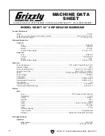
g0457 14" industrial Bandsaw (Mfg. Since 5/11)

INTRODUcTION

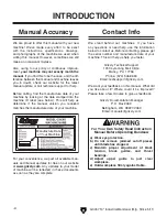
We are proud to offer this manual with your new 
machine!  We've  made  every  effort  to  be  exact 
with  the  instructions,  specifications,  drawings, 
and  photographs  of  the  machine  we  used  when 
writing this manual. However, sometimes we still 
make an occasional mistake.

Also, owing to our policy of continuous improve-
ment, 

your machine may not exactly match the 

manual

. If you find this to be the case, and the dif-

ference between the manual and machine leaves 
you  in  doubt,  check  our  website  for  the  latest 
manual update or call technical support for help.

Before calling, find the manufacture date of your 
machine by looking at the date stamped into the  
machine  ID  label  (see  below).  This  will  help  us  
determine  if  the  manual  version  you  received 
matches the manufacture date of your machine.

For your convenience, we post all available man-
uals and manual updates for free on our website 
at 

www.grizzly.com

. Any updates to your model 

of  machine  will  be  reflected  in  these  documents 
as soon as they are complete.

Manufacture Date 

of Your Machine

Manual Accuracy

We  stand  behind  our  machines.  If  you  have 
any  questions  or  need  help,  use  the  information  
below to contact us. Before contacting, please get 
the  serial  number  and  manufacture  date  of  your 
machine. This will help us help you faster.

Grizzly Technical Support

1203 Lycoming Mall Circle

Muncy, PA  17756

Phone: (570) 546-9663

Email: [email protected]

We want your feedback on this manual. What did 
you  like  about  it?  Where  could  it  be  improved? 
Please take a few minutes to give us feedback.

Grizzly Documentation Manager

P.O. Box 2069

Bellingham, WA  98227-2069

Email: [email protected]

contact Info

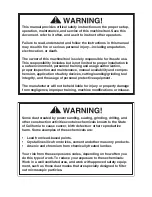
for your Own Safety Read Instruction 

Manual Before Operating Bandsaw

a)  Wear eye protection.

b) Do  not  remove  jammed  cutoff  pieces 

until blade has stopped.

c)  Maintain  proper  adjustment  of  blade 

tension,  blade  guides,  and  thrust 

bearings.

d) Adjust  upper  guide  to  just  clear 

workpiece.

e)  hold workpiece firmly against table.

Содержание G0457

Страница 1: ...AUGUST 2005 By Grizzly Industrial Inc Revised AUGUST 2011 TS Warning No portion of this manual may be reproduced in any shape Or form without the written approval of Grizzly Industrial inc FOR MACHIN...

Страница 2: ...g grinding tool integrity and the usage of personal protective equipment The manufacturer will not be held liable for injury or property damage from negligence improper training machine modifications...

Страница 3: ...ge 23 Blade Tensioning 24 Adjusting Support Bearings 24 Blade Guide Adjustments 26 SECTION 4 OPERATIONS 27 Basic Controls 27 Overview 28 Workpiece Inspection 29 Table Tilt 29 Guide Post 30 Ripping 30...

Страница 4: ...es for free on our website at www grizzly com Any updates to your model of machine will be reflected in these documents as soon as they are complete Manufacture Date of Your Machine Manual Accuracy We...

Страница 5: ...Cover Miter Gauge Assembly Table Tilt Scale Under Table Motor Dust Port Table Trunnion Hand Knob Guide Post Lock Knob Resaw Fence Resaw Fence Lock Handle Blade Guard If you have never used this type...

Страница 6: ...15 in Carton 2 Type Cardboard Content Cabinet Stand Weight 70 lbs Length x Width x Height 26 x 23 x 19 in Electrical Power Requirement 110V or 220V Single Phase 60 Hz Prewired Voltage 220V Full Load...

Страница 7: ...e Sq Tubing 0 075 in Wall Thickness Table Information Table Length 19 3 4 in Table Width 14 3 16 in Table Thickness 1 1 2 in Floor to Table Height 42 1 4 in Fence Information Locks in Front Yes Locks...

Страница 8: ...Never operate under the influence of drugs or alcohol when tired or when distracted OWNER S MANUAL Read and understand this owner s manual BEFORE using machine Untrained users can be seriously hurt EY...

Страница 9: ...EED DIRECTION Unless otherwise noted feed work against the rotation of blades or cutters Feeding in the same direction of rotation may pull your hand into the cut FORCING MACHINERY Do not force machin...

Страница 10: ...Never hold small workpieces with your fingers during a cut Always support feed the workpiece with push stick table support vise or some type of clamping fixture CUTTING TECHNIQUES Plan your cuts so yo...

Страница 11: ...n and make sure it is connected to a power supply circuit that meets the requirements in the following section For your own safety and protection of property consult a qualified electrician if you are...

Страница 12: ...ce for electric current Figure 3 Typical 5 20 plug and receptacle Grounding Prong Hot Neutral 5 20 PLUG GROUNDED 5 20 RECEPTACLE Figure 2 Typical 6 15 plug and receptacle Grounding Prong Current Carry...

Страница 13: ...side the motor wiring junc tion box To convert the machine to 110V 1 DISCONNECT MACHINE FROM POWER 2 Replace the power cord with one that match es the cord specifications under Circuit Recommendations...

Страница 14: ...4mm 1 Hex Wrench 5mm 1 Phillips Screwdriver 1 Machinist s Square 1 Ruler 1 Straightedge 1 Feeler Gauge 0 016 1 Dust Collector 1 Dust Hoses 1 Needed for Setup Your machine was carefully packaged for s...

Страница 15: ...G0457 14 Industrial Bandsaw Mfg Since 5 11 13 Hardware Recognition Chart...

Страница 16: ...1 x 20 Front Rail 2 Cap Screws M6 1 x 16 Rear Rail 2 Flat Washer 8mm Fence 1 Flange Screw Blade Tension Knob 1 Hex Bolt M8 1 25 x 80 Positive Stop 1 Hex Nut M8 1 25 Positive Stop 1 Carriage Bolts M8 1...

Страница 17: ...or power connection to prevent unsupervised use Site Considerations The unpainted surfaces are coated with a waxy oil to prevent corrosion during shipment Remove this protective coating with a solven...

Страница 18: ...binet The bandsaw body is heavy DO NOT over exert yourself while unpack ing or moving your machine get assistance from another person Figure 9 Securing the body to the stand 4 With the help of an assi...

Страница 19: ...e motor so the belt is tight then tighten the cap screws Refer to Tensioning V Belt on Page 45 to properly tension the drive belt 11 Refer to Wiring on Page 51 and wire the motor to the switch cord 12...

Страница 20: ...Attach the front rail to the front of the bandsaw table with the two M6 1 x 20 hex bolts 6mm lock washers and flat washers as shown in Figure 16 Figure 16 Installed front rail Figure 17 Handle install...

Страница 21: ...ce with a hose clamp 2 Tug the hose to make sure it does not come off Note A tight fit is necessary for proper per formance DO NOT operate the Model G0457 without an adequate dust collection system Th...

Страница 22: ...imes and watch how the blade rides on the crown of the wheel Refer to Figure 22 for an illustration of this concept If the blade rides in the center of the upper wheel and is centered on the peak of t...

Страница 23: ...g noises Strange or unusual noises must be inves tigated and corrected before operating the machine further Always disconnect the machine from power when investigating or correcting potential problems...

Страница 24: ...hould be aligned so that the miter slot is parallel to the bandsaw blade This procedure works best with a 3 4 blade installed To align the table so the miter slot is parallel to the bandsaw blade 1 Ma...

Страница 25: ...cap screws being careful not to move the fence Miter Gauge Figure 28 Squaring miter gauge to blade The miter gauge needs to be calibrated to the blade when it is first mounted in the miter slot To cal...

Страница 26: ...ime When you see the bandsaw blade start to flutter stop decreasing the ten sion 6 Now slowly increase the tension until the blade stops fluttering then tighten the tension another quarter turn 7 Look...

Страница 27: ...ew 4 Loosen the assembly lock bolt 5 Rotate the blade guide assembly side to side until the blade is perpendicular to the face of the support bearing as illustrated in Figure 30 Figure 32 Dollar bill...

Страница 28: ...guide bearings as far for ward as possible to the blade gullets and still maintain the proper support bearing spacing adjustment Figure 33 Blade guide controls Thumbscrew Cap Screw Blade Guide Bearing...

Страница 29: ...ry could get caught in machinery and cause serious personal injury Keep these items away from moving parts at all times to reduce this risk To reduce the risk of serious injury when using this machine...

Страница 30: ...e sharpen and clean blades as nec essary and make adjustments periodically to keep the saw running in top condition Use light and even pressure while cutting Light contact with the blade will permit e...

Страница 31: ...s NOT designed to cut metal glass stone tile etc cutting these materials with this saw may lead to injury Foreign Objects Nails staples dirt rocks and other foreign objects are often embed ded in wood...

Страница 32: ...support to the blade Ripping Ripping is the process of cutting with the grain of the wood stock For plywood and other processed wood ripping simply means cutting down the length of the workpiece To ri...

Страница 33: ...ber Resawing Figure 40 is the process of cutting a board into two or more thinner boards The maxi mum board width that can be resawn is limited by the maximum cutting height of the bandsaw Maximum cut...

Страница 34: ...k carefully so that the blade follows the layout line without twisting If a curve is so abrupt that it is necessary to repeatedly back up and cut a new kerf use either a narrower blade or a blade with...

Страница 35: ...erfere with the cutting Hot glue on the edges works well as do brad nails through the waste portion Be careful not to cut into the brads 3 On the face of the top piece lay out the shape you intend to...

Страница 36: ...blade width Figure 42 Blade width radii Blade Width Cutting Radius Figure 43 Raker Skip Hook tooth styles Raker Skip Hook Straight Cutting Use the largest width blade that you own The Model G0457 wil...

Страница 37: ...plication The wrong choice of blades will often produce unnecessary heat which will shorten the life of your blade A clean blade will perform much better than a dirty blade Dirty or gummed up blades p...

Страница 38: ...loves when handling saw blades Figure 44 Placing blade on the wheels To replace the blade 1 Slide the blade through the table slot ensur ing that the teeth are pointing down toward the table Note If t...

Страница 39: ...Face Shield Window T20448 Economy Clear Safety Glasses T20452 Kirova Anti Reflective Glasses T20456 Dakura Clear Safety Glasses H0736 Shop Fox Safety Glasses These glasses meet ANSI Z87 1 2003 specif...

Страница 40: ...Boeshield T 9 4 oz Spray H3788 G96 Gun Treatment 12 oz Spray H3789 G96 Gun Treatment 4 5 oz Spray Figure 49 H5408 Blade Tensioning Gauge H5408 Blade Tensioning Gauge The Blade Tensioning Gauge ensures...

Страница 41: ...b capacity These super heavy duty roller stands feature con venient hand knobs for fast height adjustment Figure 53 SHOP FOX Roller Stands G8983 G8984 G8985 G5683 Magnetic Base Light Light up your wor...

Страница 42: ...n Treatment SLIPIT or Boeshield T 9 see Section 5 Accessories on Page 37 for more details Unpainted Cast Iron Sealed and pre lubricated ball bearings require no lubrication for the life of the bearing...

Страница 43: ...l spirits after use so they won t contaminate the new grease 5 Use a small clean brush to apply NLGI 2 or equivalent automotive grade multi purpose grease to the rack After applying rotate the guide a...

Страница 44: ...Trunnions 1 DISCONNECT BANDSAW FROM POWER 2 Wipe the old grease off the bearing surfaces of the table trunnions Start with the outward side of the table trunnions Figure 57 when the table is at 0 then...

Страница 45: ...h 5 Check for broken wires or corroded disconnected connections and repair replace as necessary 6 Test replace if faulty 7 Repair replace Machine stalls or is underpowered 1 Wrong workpiece material w...

Страница 46: ...erating 1 Applying too much pressure to workpiece 2 Blade is dull 1 Feed workpiece slower See Basic Cutting Tips on Page 28 2 Replace blade Page 36 Ticking sound when the saw is running 1 Blade weld c...

Страница 47: ...nient Tensioning V Belt Tools Needed Qty Hex Wrench 6mm 1 To tension the V belt 1 DISCONNECT BANDSAW FROM POWER 2 Open the lower wheel cover 3 Loosen the motor mount screws shown in Figure 58 Figure...

Страница 48: ...ley 6 Slip the old V belt off of the wheel pulley and install the new V belt in its place 7 Install the lower wheel back onto the bearing shaft and replace tighten the wheel mount bolt 8 Position the...

Страница 49: ...instructions on Page 22 to complete this procedure Shimming Table Blade Lead Figure 62 Blade leading away from line of cut Bandsaw blades sometimes wander off the cut line when sawing as shown in Figu...

Страница 50: ...r cap screws on top of the fence 5 Skew the fence so it is parallel to the edge of the scrap piece You may need to re adjust the fence locking mechanisms to gain maxi mum adjustment 6 While maintainin...

Страница 51: ...own in Figure 63 Note For best results straighten the 2x4 with a jointer before cutting 2 Remove the fence and table then open both wheel covers 3 Make sure the guide blocks and rear sup port bearings...

Страница 52: ...els are copla nar readjust the guide blocks and rear sup port bearings and replace the wheel covers Note The blade may track slightly OFF center when the wheels are coplanar This is natural because th...

Страница 53: ...s current at the time of printing but may not match your machine If you find this to be the case use the wiring diagram inside the motor junction box CAPACITORS INVERTERS Some capacitors and power inv...

Страница 54: ...ired Start Capacitor 300MFD 250VAC Ground 4 3 2 1 110V 110V 220V Ground 1 3 4 2 Hot Hot Hot Ground Neutral Ground 5 20 Plug As Recommended 6 15 Plug As Recommended 220 VAC G Bl Wt Gn Bl Gn Wt Run Capa...

Страница 55: ...4 100 102 101 111 96V2 97 76 121 157 89 150 151 164 103 158 1 4 95 94 5 66 104 64 104 105 66 159 160 72 62 69 68 63 59 60 61 67 58 33 29 27 8 7 6 55 23 11 12 26 31 22 25 162 34 161 28 32 30 51 54 37 4...

Страница 56: ...W M6 1 X 35 95 PFS11M FLANGE SCREW M6 1 X 10 35 PFH27M FLAT HD SCR M4 7 X 6 96V2 P0457096V2 MOTOR 2HP 1PH 220 110V V2 05 11 36 P0457036 RACK 96V2 1 P0457096V2 1 MOTOR FAN COVER 37 P0457037 HAND KNOB M...

Страница 57: ...X127 TABLE INSERT 150 P0457150 POINTER BRACKET 127 P0457127 TABLE PIN 151 PFS12M FLANGE SCREW M5 8 X 12 128 P0457128 TABLE 157 P0457157 LEVER PLATE 129 PB73M HEX BOLT M10 1 5 X 50 158 PB09M HEX BOLT M...

Страница 58: ...PH7587003 FENCE SUPPORT MOUNTING ROD 149 19 P0457149 19 REAR RAIL END CAP 149 4 PH7587004 LOCK ROD 149 20 PHTEK3M TAP SCREW M3 5 X 8 149 5 PH7587005 SPRING PIECE 149 21 P0457149 21 SCALE 149 6 PH75840...

Страница 59: ...07 REF PART DESCRIPTION REF PART DESCRIPTION 301 PCB01M CARRIAGE BOLT M8 1 25 X 20 306 P0457306 LATCH ASSEMBLY 302 P0457302 STAND 307 PW02 FLAT WASHER 3 8 303 P0457303 FLANGE NUT M8 1 25 308 PN08 HEX...

Страница 60: ...esuming operations For replacements contact 800 523 4777 or www grizzly com REF PART DESCRIPTION REF PART DESCRIPTION 401 P0457401 MACHINE ID LABEL 407 PLABEL 19 HANDS NEAR BLADE LABEL 402 PLABEL 12 R...

Страница 61: ...metalworker ____ 0 2 Years ____ 2 8 Years ____ 8 20 Years ____20 Years 6 How many of your machines or tools are Grizzly ____ 0 2 ____ 3 5 ____ 6 9 ____10 7 Do you think your machine represents a good...

Страница 62: ...LINE FOLD ALONG DOTTED LINE GRIZZLY INDUSTRIAL INC P O BOX 2069 BELLINGHAM WA 98227 2069 Place Stamp Here Name_______________________________ Street_______________________________ City______________S...

Страница 63: ...shall be tried in the State of Washington County of Whatcom We shall in no event be liable for death injuries to persons or property or for incidental contingent special or consequential damages arisi...

Страница 64: ...Buy Direct and Save with Grizzly Trusted Proven and a Great Value Since 1983 ORDER 24 HOURS A DAY 1 800 523 4777 Visit Our Website Today For Current Specials...

Отзывы: