


-30-
g0457 14" industrial Bandsaw (Mfg. Since 5/11)
To adjust guide post:
1. Make sure that the blade tension, blade
tracking, support bearing, and blade guides
are adjusted correctly.
2. loosen the guide post lock knob shown in
figure 37.
3. raise/lower the guide post with the adjust-
ment knob to within 1" from the top of the
workpiece to the bottom of the blade guide
assembly.
4. lock the guide post in place with the lock
knob.
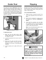
Guide post
figure 37. guide post controls.
the guide post, shown in
figure 37, connects the
upper blade guide assembly to the bandsaw. the
guide post allows the blade guide assembly to
move up or down via a rack and pinion. in order
to cut accurately, the blade guide assembly must
be no more than 1" from the top of the workpiece
at all times—this positioning provides the greatest
support to the blade.
Ripping
ripping is the process of cutting with the grain of
the wood stock. For plywood and other processed
wood, ripping simply means cutting down the
length of the workpiece.
To rip with the Model G0457:
1. Adjust the fence to match the width of the
cut on your workpiece and lock the fence in
place.
2. Make sure the bandsaw is properly set up
and adjusted as described in
SEcTION 3:
SETUp.
3. Slowly feed the workpiece into the blade
and continue with the cut until the blade is
completely through the workpiece.
figure 38
shows a typical ripping operation.
Note:
If you are cutting narrow pieces, use a
push stick to protect your fingers.
figure 38. ripping with a push stick.
NEvER place fingers or hands in the line of
cut. In the event that something unexpected
happens, your hands or fingers may be
pulled into the blade. ALWAyS use a push
stick when ripping narrow pieces. failure to
follow these warnings may result in serious
personal injury!
Adjustment
Knob
lock
Knob
guide post


