background image


Note:  Some  front  forks  have  compression 
adjuster  on  one  leg  and  rebound  adjuster  on 
the other leg. In this case, the servo motors are 
mounted one on the right leg and one on the 
left  leg.  Other  type  of  forks  (such  as  the  BPF) 
have  both  adjustments  on  both  legs.  In  this 
second case, the 1st servo motor is mounted on 
right  leg  (in  proximity  of  the  compression

’s


adjuster) and the 2nd servo motor is mounted 
on  the  left  leg  (in  proximity  of  the 

rebound’s 

adjuster). 


3.1 COMPRESSION 


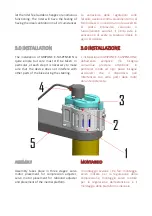
Fix  the  servo  motor  (4)  to  the  plastic 
support  (3),  using  the  M3  screws.  Do  not 
lock the screws yet.  


Fit  the  tool  bit  (screwdriver  or  allen  key 
type) into the shaft (2) of the servo motor.  


Fix the plastic support (3) to the support (1) 
using the three M4 screws and nuts  


Fix the support (1) to the steering plate (5) 
using the double-sided adhesive supplied.  


If necessary, add a plastic ty-rap to better 
secure the device to the top plate.  


Position the servo motor in such a way as 
to put the tool bit (screwdriver or Allen key) 
in contact with the hydraulic compression 
adjuster.  


Once you have found the correct position, 
fasten the screws. 

 
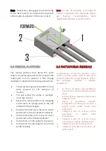
Note: the structure that hold the servo motor is 
made to be adjusted horizontally and vertically. 
Find the right position to allow a proper action 
of the servo motor. 


3.2 REBOUND 

 
Repeat  the  steps  described  in  paragraph  3.1 
using the other leg.  
 

Nota: Alcune forcelle hanno la regolazione 
della compressione su un gambale e quello 

dell’estensione sull’altro. 


In  questo  caso  i  servo  motori  vengono 

montati uno su un gambale e uno sull’altro.


Altre  forcelle  (come  le  BPF)  hanno 
entrambe  le  regolazioni  su  entrambi  i 
gambali. In questo secondo caso, il 1° servo 
motore viene montato su un gambale (sulla 
regolazione  della  compressione)  e  il  2° 

servo  motore  viene  montato  sull’altro 

gambale 

in 

corrispondenza 

della 

regolazione dell’estensione.


3.1 COMPRESSIONE 


Fissare il servo motore (4) al supporto 
plastico  (3),  tramite  le  viti  M3.  Non 
bloccare le viti. 


Inserire  l’inserto  a  cacciavite  o  a 

brugola  nel

l’albero  (2)  del

  servo 

motore. 


Fissare  il  supporto  plastico  (3)  al 
supporto (1) tramite le tre viti M4 e i 
dadi 


Fissare  il  supporto  (1)  alla  piastra  di 
sterzo tramite il bi-adesivo fornito. 


Aggiungere se necessario una fascetta 
in  plastica  per  assicurare  meglio  il 
dispositivo alla piastra superiore. 


Posizionare  il  servo  motore  in  modo 
tale da mettere a 

contatto l’inserto (a 

cacciavite  o  a  brugola)  con  la 
regolazione 

idraulica 

della 

compressione. 


Una  volta  trovata  la  posizione 
corretta, fissare le viti del supporto 


3.2 ESTENSIONE 

 
Ripetere  i  punti  descritti  al  paragrafo  3.1 

utilizzando l’altro gambale. 


Содержание E-SUSPENSION

Страница 1: ...User manual PERFORMANCE IMPROVING DEVICES E SUSPENSION transform your fork into an electronic suspension Hardware version v 002 ...

Страница 2: ...ility you lose speed of reaction and so on Thanks to GRIPONE E SUSPENSION this problem no longer exists because through two 1 0 INTRODUZIONE GRIPONE E SUSPENSION è un dispositivo elettro meccanico che può essere applicato a tutte le forcelle per trasformarle in sospensioni elettroniche Le regolazioni delle sospensioni sono un compromesso tra supporto sensibilità velocità di reazione e stabilità Se...

Страница 3: ... della forcella posizionati nel tappo del gambale La forma del tappo e la marca della forcella non sono importanti GRIPONE E SUSPENSION può essere installato su tutte le marche di forcelle e su tutte le forcelle ce hanno le cartucce aftermarket example esempio 2 0 HOW IT WORKS GRIPONE E SUSPENSION s able to recognize 5 different situations braking trail braking mid corner acceleration and changes ...

Страница 4: ... to make sure that the device does not interfere with other parts of the bike during the steering 3 0 INSTALLAZIONE L installazione di GRIPONE E SUSPENSION è abbastanza semplice ma bisogna comunque prestare attenzione In particolar modo ad ogni passo bisogna assicurarsi che il dispositivo non interferisca con altre parti della moto durante la sterzata ASSEMBLY Assembly takes place in three stages ...

Страница 5: ...ally Find the right position to allow a proper action of the servo motor 3 2 REBOUND Repeat the steps described in paragraph 3 1 using the other leg Nota Alcune forcelle hanno la regolazione della compressione su un gambale e quello dell estensione sull altro In questo caso i servo motori vengono montati uno su un gambale e uno sull altro Altre forcelle come le BPF hanno entrambe le regolazioni su...

Страница 6: ... the servo motor positioned on the compression adjuster Connect the cable 2 to the servo motor positioned on the rebound adjuster Connect pin 1 of the cable 3 to ground Connect pin 4 of the cable 3 to 12 Volts under the key 3 3 PIATTAFORMA INERZIALE La piattaforma inerziale che comanda i servo motori dovrebbe essere piazzata nella parte anteriore nella moto ma ogni posizione va bene Nel montaggio ...

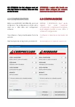
Страница 7: ... you must configure it The configuration is simple and is done via a USB cable and configuration software The software is freely downloadable from the web site download gripone com gripone_esuspension 4 0 CONFIGURAZIONE GRIPONE E SUSPENSION deve essere regolato per poter funzionare correttamente La regolazione è semplice e viene eseguita tramite un cavo USB e il software di configurazione Il softw...

Страница 8: ...rgin of closing INTENSITY Enter the intensity you want to have from the device With intensity 1 the device will apply minimal changes With intensity 2 the device Una volta scaricato e installato il software avvia GRIPONE E SUSPENSION facendo doppio click sull icona del menu Start La finestra principale è suddivisa in due aree COMPRESSION compressione e REBOUND estensione Per ognuna di queste aree ...

Страница 9: ...iattaforma inerziale Inserire i valori dei 4 parametri per la regolazione della compressione e la regolazione dell estensione Collegare il cavo USB alla piattaforma inerziale e attendere che sia rilevata tramite la scritta CONNECTED premere SEND CONFIGURATION INERTIAL PLATFORM CALIBRATION The first time you use GRIPONE E SUSPENSION you must calibrate the inertia platform By this procedure GRIPONE ...

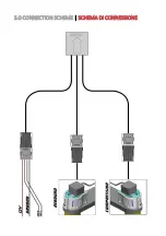
Страница 10: ...5 0 CONNECTION SCHEME SCHEMA DI CONNESSIONE ...

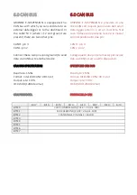
Страница 11: ... 0 CAN BUS GRIPONE E SUSPENSION è provvisto di una linea CAN con la quale puoi inviare dati ad un data logger esterno o ad un cruscotto Nel cavo 3 dove sono presenti la 12 e la massa sono disponibili altri due pin CAN H pin 3 CAN L pin 2 Collega questi due pin e la massa per inviare dati via CAN bus ad un altro dispositivo SPECIFICHE CAN BUS Baud rate 1Mbs Format Intel LSB CAN 2 0B 11 bit Output r...

Страница 12: ...is designed owned and made by GUBELLINI s a s di Diego Gubellini C Via Euridia Bergianti 10 B 40059 Medicina BO Italy P IVA VAT IT03466001207 www gripone com info gripone com ...

Отзывы: