G-SWS
Assembly and Operating Manual
6 Assembly
4
Depending on the size one (SWS050 to 080) or two (SWS100 to 250) fitting bores according to
ISO 9409 are available on the robots or grippers side.
CAUTION! Risk of pinching the fingers when closing the SWS
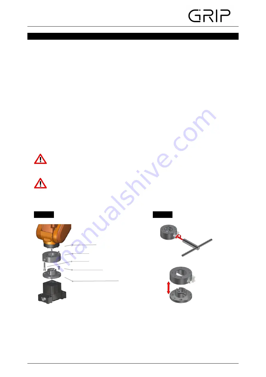
When assembling, the upper and lower assemblies do not have to be inserted
into each other as far as they will go. By turning the semi-cylindrical bolt, the
lower assembly is pulled around the locking stroke (see technical description
„VH“).
The upper assembly of the SWS Connector is mounted on the robot flange, the manipulator or
similar actuators. It can be centered with the help of a centering disc. The angular orientation is
determined by means of a fitting bore. The lower assembly is mounted on grippers, measuring
instruments or other tools. If the SWS Connector can not be installed directly, adapter flanges
must be used. Use screws according to DIN 912. For the sizes 50, 63 and 80, screws according to
DIN 7984 are to be used on the gripper side. The screw-in depth of the screws must be observed.
We recommend the use of a "medium-tight" screw lock.
Optionally, the SWS can be provided with a MEK Energy Coupling. To mount the MEK the "E"
option must be specified when ordering the SWS. The MEK is available in different versions. The
MEK enables the simultaneous coupling of electrical and pneumatic lines when opening or closing
the SWS. The MEK is mounted with two cylinder screws to the upper and lower assemblies. For
further installation instructions, please refer to the assembly and operating instructions of the MEK.
CAUTION!
Perform assembly work only when the power supply is switched off!
Image 1
Image 2
Robot flange
Upper assembly
ISO 4762
DIN 7984/ ISO 4762
Lower assembly
(MGW050-125 and SWS160-250)


