Shuttle Brewers & Airpot/Shuttle Brewers
Page 33
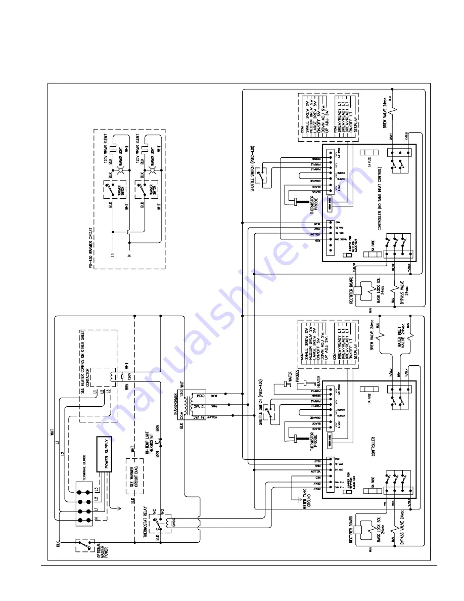
Wiring Diagram - Precision Brew 430 Series
Models APB-430V2, APBVSA-430V2, and APBIC-430V2
Страница 1: ...oblems 20 Heating Problems 22 Brewing Problems 24 Precision Brew Control Board 26 Parts List 27 Parts Photos 28 VS 1 5 S Cleaning and Sanitizing 32 Wiring Diagrams 33 Grindmaster Corporation 2004 PRINTED IN U S A Grindmaster Cecilware 4003 Collins Lane Louisville KY 40245 USA 502 425 4776 800 695 4500 USA Canada only 800 568 5715 Technical Service Only FAX 502 425 4664 www grindmaster com 0511 For...
Страница 2: ......
Страница 3: ...id of machine Located on APB 330V2 APB 330V2E230 APB 430V2 and APB 430V2E230 lower front decal Order part A546 434 for APB 330V2 Order part A546 435 for APB 430V2 Part A546 213 Located on front splash panel Part A71949 Located on brew baskets Shuttle Brewers Airpot Shuttle Brewers Page 3 CAUTION Remove with care Hot liquid in brew basket could cause burns Located on APBIC 330V2 APBIC 330V2E230 APB...
Страница 4: ...tric and water hook up locations are behind the front panel Remove the four screws fastening this panel for access to these connections Water Hook up 1 The water line may enter through holes on the rear or the bottom of the brewer Use the right hand opening for water 2 Use 3 8 copper or flexible water line to prevent strain Do not use low temperature plastic tubing The connection to the fill valve...
Страница 5: ...d type THHN wires may be used Use only copper conductors 4 Standard connection is 1 phase 3 wire Connect the two lines to L1 and L2 on the terminal block If the brewer is wired for three phase a lug L3 is provided on the terminal block Neutral line should be connected to the N terminal Alternately if no neutral is available the brewer can be wired accordingly by connecting L1 to position marked L1...
Страница 6: ...ill be locked in place until drip cycle is finished CAUTION Coffee basket contains very hot water until the drip is completed Early removal of a dripping basket could result in burns 8 Dump the grounds from the basket and rinse for the next brew Coffee is ready to serve 9 The Shuttle may be placed on remote warming stations Use caution when moving a full Shuttle Installation cont Start up 1 Flip p...
Страница 7: ...5 7 96 5 199 92 8 4000 204 8 96 0 198 92 2 4500 203 9 95 5 197 91 7 5000 203 95 0 196 91 1 5500 202 94 4 195 90 6 6000 201 1 93 9 194 90 0 6500 200 2 93 4 193 89 4 7000 199 3 92 9 192 88 9 7500 198 3 92 4 191 88 3 This brewer can be set for maximum water temperature of 205 F 96 C The boiling point of water is lower as altitude increases The setpoint temperature of the brewer should be maintained b...
Страница 8: ... Pre infusion and the pulses At the end of the brew time the display will scroll driP while the brew basket drains itself At the end of the drip cycle the display will scroll doneE for 30 seconds then turn off Energy Savings Mode If enabled when the brewer is idle for three 3 hours this feature will allow the water tank to lower its holding temperature to 120 F The display will scroll SLEEPIng whi...
Страница 9: ...the gourmet sprayhead Bypass ratio is the last global program parameter to be set The following are the individual brew portion parameters Each portion button can have individual brew sequences 7 Br time Brew time Choose between 0 01 to 6 00 minutes This time setting controls the brew volume The brewer brews at a rate of 1 5 gallons in four minutes 48 ounces per minute 0 8 ounces per second The La...
Страница 10: ... 6 00 minutes 2 PrE inFuSion Choose OFF to 2 00 minutes 3 PrE inFuSion oFF Choose 0 05 to 2 00 minutes 4 PuLSE br Pulse Brewing Choose OFF to 10 5 PuLSE on Pulse ON time Choose 0 05 2 00 minutes 6 PuLSE oFF Pulse OFF time Choose 0 05 2 00 minutes 7 By PASS Set bypass volume Choose OFF 25 8 CoPY to LEFt Choose YES or no The sequence of programming for the Small portion is as follows refer to Table ...
Страница 11: ... TO 2 00 TO PRESS AND HOLD UP DOWN ARROWS FOR 5 SECONDS DISPLAY WILL READ AS FOLLOWS OG G O S S OR READING OR TO BREW TIME BYPASS RATIO LOW TEMP LOW TEMP NO BREW OR DISPLAY TEMP SCALE TANK TEMP 170 202F OR OR BREW TIME 01 TO 6 00 ENERGY MODE ADVANCE NO BREW DRIP TIME PERCENT OF BREW ENERGY MODE ADJUST DRIP TIME continued on next page ...
Страница 12: ...e for Large Left Portion cont Table 1 cont PRE INFUSION ADJUST TO PULSE OFF TIME 0 05 2 00 PULSE ON TIME 0 05 2 00 COPY TO LEFT OF PULSES OR READING DISPLAY ADVANCE PULSE ON PULSE OFF BY PASS OFF TO 25 PERCENT PULSE BREW OFF 1 10 05 TO 2 00 TO PRE INFUSION OFF TIME TO ...
Страница 13: ... OFF 1 10 DISPLAY WILL READ AS FOLLOWS TO PULSE BREW OF PULSES PRESS AND HOLD UP DOWN ARROWS FOR 5 SECONDS TO ADJUST PULSE OFF BY PASS TO OG G O S S READING DISPLAY ADVANCE BREW TIME BREW TIME 01 TO 6 00 PRE INFUSION PRE INFUSION TIME OFF TO 2 00 PRE INFUSION OFF TO 25 PERCENT 05 TO 2 00 TO PRE INFUSION OFF TIME PULSE ON continued on next page ...
Страница 14: ...tle Brewers Airpot Shuttle Brewers Programming Sequence for Medium Portions cont Table 2 cont DISPLAY WILL READ AS FOLLOWS COPY TO LEFT PRESS AND HOLD UP DOWN ARROWS FOR 5 SECONDS OR DISPLAY ADJUST READING ADVANCE ...
Страница 15: ...FOR 5 SECONDS DISPLAY WILL READ AS FOLLOWS ADVANCE OFF 1 10 ADJUST READING OG G O S S 05 TO 2 00 DISPLAY BREW TIME 01 TO 6 00 BREW TIME PULSE OFF TIME 0 05 2 00 PRE INFUSION PRE INFUSION TIME OFF TO 2 00 TO PRE INFUSION PULSE ON TIME 0 05 2 00 TO COPY TO LEFT OR PULSE OFF PULSE ON PULSE BREW OF PULSES PRE INFUSION OFF TIME TO ...
Страница 16: ...s with one gallon 2 3 full of hot water 12 Pour into the Shuttle liners the recommended concentration of urn cleaner excessive amounts of cleaner will attack the stainless steel Urn cleaners that have been used successfully DIP IT TABZ Super Concentrate manufactured by Reckitt Benckiser Inc manufactured by Urnex Brands Inc 1655 Valley Road 170 Ludlow Street Wayne NJ 07474 Yonkers NY 10705 800 228 ...
Страница 17: ...Brewer may contain over 5 gallons 19 0L of hot water 1 Prepare a heat resistant container to drain tank water into 2 Disconnect power to the brewer 3 Remove the front access panel 4 Pinch or clamp the silicone hose connected to fill valve 5 Disconnect hose from outlet barb on fill valve 6 Place hose over drain and release clamp 7 Allow the tank to drain completely NOTE It may be necessary to pinch...
Страница 18: ... will scroll donE to show completion of a system restore Upon a successful restore the original factory settings will override all changes The brew counters are not affected Factory Specific Features The following sections describe features that are not intended to be used by the end user These features instead are intended to help Grindmaster set up and test the machine Factory Field Test Menu Th...
Страница 19: ...eater level If 500 water level not at the heater level 9 Show Input Display scrolls InPut Input Test Mode 10 Input Test Press each key and the display will show a number related to that key Right Side On Off 1 advances test Up 5 Down 3 Large Brew 4 Medium Brew 2 Small Brew 0 Basket Switch 17 Left Side On Off 9 Up 13 Down 11 Large Brew 12 Medium Brew 10 Small Brew 8 Basket Switch 16 11 Show Output ...
Страница 20: ...ctions and reset controller If error reoccurs replace thermistor ER3 Thermistor is reading out of range Check tank temperature Replace thermistor ER4 No heat is detected See Heating Problems See Heating Problems Filling Problems Problem Possible Causes Service Check Remedy Overfilling water tank when power is Off Fill valve not sealing properly Check to see if water enters tank continuously usuall...
Страница 21: ...onnecting terminals See wiring diagram for more information Ensure there is proper voltage across terminal block Check wiring diagram for more information Disconnect quick disconnect on secondary side of transformer at quick disconnect between yellow and blue wires Check for 24 Vac between blue and yellow wires Establish electrical power to unit Establish water supply to unit If there is not 120V ...
Страница 22: ...re and there is 24 Vac across fill valve terminals replace fill valve Heating Problems Problem Possible Causes Service Check Remedy Tank does not heat No electrical power to equipment No power to control board Check for proper voltage at terminal block Check circuit breaker on supply circuit Check for proper voltage across transformer primary terminals by disconnecting terminals See wiring diagram...
Страница 23: ...to ensure connections from relay to thermal cut out and from thermal cut out to contactor and from contactor to proper ter minal of terminal block are secure See wiring diagram for more info mation Ensure that coil on heater relay is energized by ensuring that there is 24 VDC between the gray and blue wires attached to the relay Remove the black and brown wires from the relay and check for an open...
Страница 24: ...tions between N terminal of contactor coil and terminal block If the contactor coil is energized and there is an open circuit across any of the contactor poles replace contactor If resistance is much less than 8 Ohms or much more than 15 Ohms replace heater s If 5 pin connector is securely attached to control board and all connections are secure and functioning except there is not 120 Vac across c...
Страница 25: ...ces operating Plumb water supply so that water pressure is not significantly affected by other appliances Brew cycle will not start Optional momentary switch to indicate container in place not engaged or faulty Brew circuit connections not secure Brew valve faulty Touchpad faulty Check to see that container fully engages switch Check for continuity across switch when switch is engaged Check to see...
Страница 26: ...ve not closing completely Water in tank boiling Visually inspect brew valve at hose connections Remove sprayhead and determine if drip is coming from overflow Clean lime from valve Seat cup or entire valve may need replacement Reduce tank temperature If you still need help call our Service Department at 800 695 4500 USA and Canada only or 502 425 4776 Monday Friday 8 00 am 6 00 pm EST or an author...
Страница 27: ...230V models A531 076 230VAC coil 32 Transformer 120 208 240 100W A554 137 33 Valve Brew 24VAC PB A537 184V 34 Valve Bypass 24VAC PB A537 183V 35 Solenoid Basket Lock 24vdc A554 135 36 Touchpad PB Series A530 065 37 N A N A 38 Spray Elbow A518 054 39 Tee Barbed 3 8 KYNAR A548 172 40 Hose Overflow A585 016 41 Hose Silicone A512012 42 Elbow Silicone A548 129 Reference Tank Lid Picture 50 Element Ht 5...
Страница 28: ...Page 28 Shuttle Brewers Airpot Shuttle Brewers Front View refer to key on page 27 Lower Warmer refer to key on page 27 APB 430V2 pictured 23 23 22 21 20 21 22 6 5 1 7 3 4 2 ...
Страница 29: ...Shuttle Brewers Airpot Shuttle Brewers Page 29 Top View refer to key on page 27 42 30 34 Tank Lid refer to key on page 27 3 Heater Model shown 50 52 51 50 36 35 38 35 32 36 52 ...
Страница 30: ... Clip A548 142 6 Lid Stopper w O Ring A548 140 A61365 S S Cover used until August 2001 5 6 4 3 2 1 Shuttle Parts List for APB 330V2 and APB 430V2 A537 055 Handle A522132 Bonnet Nut A522120 Spring A537 047 Plastic Stem A522102 Silicone Seat Cup Upper Faucet Part A537 049 Gauge Assembly Part A718 018 A318 119P Top Gage Fitting A522026 Washer Upper Gage A555 001 Gage Shield A522031 Gage Glass A522027...
Страница 31: ... Tray Top A517 018 1 6 Self Tapping Screw 5 A539 217 4 7 Rubber Foot A548 161 4 8 Plastic Insert A548 162 3 9 Self Tapping Scres 75 A539 218 3 ITEM NO Title PART NUMBER VS S QTY 1 Stand Body A548 157 1 2 Tray for Stand A548 159 1 3 Stand Base A548 158 1 4 Tray Top A517 018 1 5 Stand Top Plate A517 019 1 6 NUT M4 W Nylon Insert A540 237 4 7 Self Tapping Screw 5 A539 217 4 8 Rubber Foot A548 161 4 M...
Страница 32: ...nitizing body assembly a Remove unit from the base only when using VS S with VS 1 5 b Completely fill the unit with cleaning solution Using a clean cloth wipe the unit thoroughly c Rinse unit thoroughly with fresh water d Remove faucet shank and sight gauge from unit and place in cleaning solution e Open lid on the bottom of the unit and remove silicon tube Tank to Faucet Tube and place in cleanin...
Страница 33: ...Shuttle Brewers Airpot Shuttle Brewers Page 33 Wiring Diagram Precision Brew 430 Series Models APB 430V2 APBVSA 430V2 and APBIC 430V2 ...
Страница 34: ...Page 34 Shuttle Brewers Airpot Shuttle Brewers Wiring Diagram Precision Brew 330 Series Models APB 330V2 APBVSA 330V2 and APBIC 330V2 ...
Страница 35: ...Shuttle Brewers Airpot Shuttle Brewers Page 35 Wiring Diagram APB 430V2E230 APBVSA 430V2E230 APBIC 430V2E230 Single or Three Phase Models ...
Страница 36: ...Page 36 Shuttle Brewers Airpot Shuttle Brewers Wiring Diagram APB 330V2E230 APBVSA 330V2E230 APBIC 330V2E230 Brewers ...
Страница 37: ... YDF 7 5 1 7 7 5 7 1 YGF 7 6 2 62 3 66 9 9 5 7 YDF 5281 21752 5 5 7 6 877 6 7 7 50 6725 352 7 5 7 5 352 6 32 5 0 67 5 237 21 1 75 16 250 5 9 2 32 5 6833 51 7 03 0 7 7 50267 7 51 W 6 50 5 5 8 7 7 20 9 8 20 7 51 7 7 50 1 2 7 217 725 5 7 6 2 62 3 66 9 9 7 9 8 YGF 5 9 9 5 7 YDF 7 7 50 5 7 50 5 7 9 505 07 9 505 07 6 7 50 5 7 3 02 6 1 50 5 7 6 7 9 7 6 877 6 7 25 8 9 2 4ġ4 5 0 4ġ4 5 0 7 5 5 7 2 5 2 ...
Страница 38: ...330V2 and APBIC 330V2 9 9 YDF 7 5 1 7 7 5 7 1 3 66 9 9 YDF 5281 21752 5 6 877 6 7 7 50 6725 352 7 5 7 5 352 6 32 5 0 67 5 237 21 1 75 16 250 5 9 2 32 5 6833 51 7 03 0 7 7 50267 7 51 W 6 50 5 5 8 7 7 20 9 8 20 7 51 7 7 50 1 2 7 6 2 62 8 YGF 5 9 9 YDF 7 50 5 7 9 505 07 3 02 6 1 50 5 7 6 7 9 25 8 9 4 5 0 7 1 7 5 217 725 7 5 5 7 2 5 2 ...
Страница 39: ...YDF 7 5 1 7 7 5 7 1 YGF 7 6 2 62 3 66 9 9 5 7 YDF 5281 21752 5 5 7 6 877 6 7 7 50 6725 352 7 5 7 5 352 6 32 5 0 67 5 237 21 1 RU 75 16 250 5 9 2 32 5 6833 51 7 03 0 7 7 50267 7 51 W 6 50 5 5 8 7 7 20 9 8 20 7 9 51 7 7 50 1 2 7 217 725 5 7 6 2 62 3 66 9 9 7 9 8 YGF 5 9 9 5 7 YDF 7 7 50 5 7 50 5 7 25 9 505 07 25 9 505 07 6 7 50 5 7 3 02 6 50 5 7 6 7 9 7 6 877 6 7 25 8 211 7 335235 7 25 92 7 6833 9 2...
Страница 40: ...E230 APBIC 330V2E230 9 9 YDF 7 5 1 7 7 5 7 1 3 66 9 9 YDF 5281 21752 5 6 877 6 7 7 50 6725 352 7 5 7 5 352 6 32 5 0 67 5 237 21 1 RU 75 16 250 5 9 2 32 5 6833 51 7 03 0 7 7 50267 7 51 W 6 50 5 5 8 7 7 20 9 8 20 7 9 51 7 7 50 1 2 7 217 725 6 2 62 8 YGF 5 9 9 YDF 7 50 5 7 25 9 505 07 3 02 6 50 5 7 6 7 9 25 8 211 7 335235 7 25 92 7 6833 9 4 5 0 7 1 7 5 7 5 5 7 2 5 2 ...
Страница 41: ...Shuttle Brewers Airpot Shuttle Brewers Page 41 Wiring Diagram Heater Configuration 3 Heater ...
Страница 42: ...Wiring Diagram Heater Configuration 1 Heater Page 42 Shuttle Brewers Airpot Shuttle Brewers ...
Страница 43: ...Shuttle Brewers Airpot Shuttle Brewers Page 43 Control Board all PrecisionBrew V2 0 models Refers to software version number Subject to change ...
Страница 44: ...776 Fax 502 425 4664 1 800 695 4500 USA Canada only P O Box 35020 Louisville KY 40232 USA www grindmaster com email info grindmaster com Grindmaster Corporation 2011 PRINTED IN USA 0511 Form AM 346 02 Part A090 842 ...