


Crathco
®
5000 Series Manual
Page 11
Consistency Control - Overview (cont.)
In the “standby” mode the control board senses the temperature of the product in the barrel. The drive motor is
cycled on time only. It will operate for 2 minutes ON then 18 minutes OFF as long as it is in “standby”. The com-
pressor and drive motor are cycled independently for the barrel in the “standby” mode. Once the barrel thermistor
signals to the board, the board will start the compressor and the barrel solenoid valve will open as refrigeration is
required. It will continue to run until satisfied. The plunger switch is disabled and the drive motor will not start when
the plunger is opened. The hopper is still controlled by temperature. If the thermistor signals a raise in temperature
the compressor will start and the hopper solenoid valve will be opened. It will continue to run until satisfied.
In the “clean” mode the drive motor will run continuously. (The compressor will not run in the “clean” mode.) This is
for emptying out product for cleaning purposes.
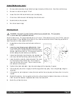
There are eleven (11) lights on the circuit board that indicate the following: (See Figure I)
BARREL (D1) - Illuminated when the freezing cylinder (barrel) has achieved the pre-set temperature in the
"Standby" mode.
HOPPER (D2) - Illuminated when the hopper has achieved the pre-set temperature in the "Standby" mode.
WASH (D3) - Illuminated when the mode switch is in the wash or "Clean" position.
FREEZE (D4) - Illuminated when the mode switch is in the "Freeze" mode.
DISPENSE (D5) - Illuminated when the dispensing valve is open calling for both the compressor and drive
motor to operate.
GREEN CONSISTENCY (D6) - Off when the motor and compressor are off. Illuminated when the
compressor and dasher are bringing product to preset consistency. Blinks as preset consistency is
achieved and then goes out.
RED CONSISTENCY (D7) - Blinks as preset product consistency is approached. Glows steadily when
preset consistency is achieved and then goes out.
COIL (D8) - Compressor contactor energized
COIL (D9) - Drive motor coil energized
COIL (D10) - Hopper refrigeration solenoid coil energized
COIL (D11) - Freezing cylinder refrigeration solenoid coil energized
Figure I
Electronic Control Board
Содержание Crathco 5311
Страница 2: ......
Страница 42: ...Page 42 Crathco 5000 Series Manual 5511 Electrical Components 5511 0102 057 3 20 00 ...
Страница 44: ...Page 44 Crathco 5000 Series Manual 5311 Front Electrical Box CR CR CR CR ...
Страница 45: ...Crathco 5000 Series Manual Page 45 5511 Front Electrical Box 5511 0101 057 3 20 00 ...
Страница 53: ...Crathco 5000 Series Manual Page 53 5311 Spinner Hook Up with Timer Wiring Diagram ...
Страница 54: ...Page 54 Crathco 5000 Series Manual 5511 Spinner without Timer Hook Up Wiring Diagram 5511 0100 057 9 14 00 ...
Страница 58: ...Page 58 Crathco 5000 Series Manual 5311 Ladder Diagram 115V 60 Hz ...
Страница 59: ...Crathco 5000 Series Manual Page 59 5511 Ladder Diagram 208 230V 50 Hz 5511 0103 057 3 20 00 ...
Страница 68: ...Refrigeration Circuit Page 68 Crathco 5000 Series Manual ...
Страница 70: ......
Страница 71: ......