


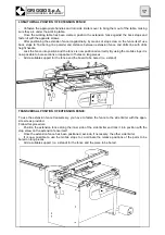


The extension fence is used to make a set of larger holes than the ones the machine can make or to
bore large pieces. To use the extension fence you usually have to exclude side limiters completely or
partially. To position the extension fence you usually have to exclude side limiters completely or partially
and to set the spindlehead at 90°. If you use the extension fence longitudinally, we advise you to ex-
clude side limiters completely, since it is possible to use mobile reference stops on the extension fence
itself to position the piece to be worked. (The extension fence is provided with 4 mobile stops with posi-
tioning screws, stop screw and extension fence clamping device).
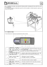
16.6 HOW TO USE REFERENCE STOPS FOR STANDARD 0°-90°WOODWORKING
Side rails and back stops are used to position the piece to be worked in a standard working cycle.
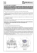
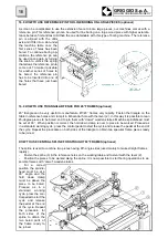
With spindlehead at 90° and spindle unit locked into position:
-
Set side rails at the right distance from drills that will be used and fasten them.
-
Position the hold-down cylinder (or hold-down cylinders) (3) on the table where the piece to be
worked will be located.
-
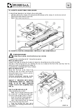
Position the piece to
be bored against side limit-
ers and use them as rails
to position the piece under
the hold down clamps and
right against the rack.
-
Now position the stops
(2) over the piece to be
bored, lower stop refer-
ence block itself on the
piece, and clamp the stop
itself with the handle.
-
The piece is in the right
position and it is now pos-
sible to start the working
cycle by pressing the pedal
that starts drills feed with
engine switched on (make
sure engine switch is on).
At the same time hold
down clamps will lock the
piece into position.
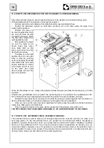
16.7 HOW TO USE EXTENSION FENCE (3000 MM STANDARD)
When the first phase is over, release the pedal to release the piece and take the bored piece out of the
machine.
Unfasten the spindlehead unit and switch the overturning lever to reposition the spindlehead at 90°.
Once the head has been repositioned and locked into position, the second phase can begin:
-
Position the piece that has to be joined to one that has just been worked against the side limiter un-
der the hold down clamp (or hold down clamps) (3) and against the back stop block.
-
Once you are sure the piece has been positioned correctly, press the pedal to activate hold down
clamp lock, drills rotation and drills feed.
-
Once the pedal is released, the piece will be released and the working cycle will be over.
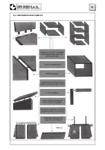
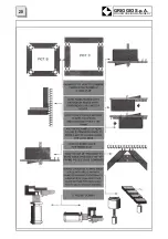
THE TWO PIECES THAT HAVE BEEN OBTAINED (0° -90°) ARE NOW READY TO BE JOINED
GRIGGIO S.p.A.
WOODWORKING MACHINERY
16
Содержание GF 21
Страница 2: ......
Страница 4: ......
Страница 23: ...16 10 WOODWORKING EXAMPLES 19 GRIGGIO S p A WOODWORKING MACHINERY ...
Страница 24: ...GRIGGIO S p A WOODWORKING MACHINERY 20 ...
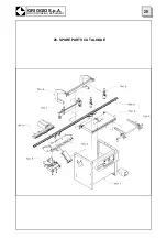
Страница 33: ...29 GRIGGIO S p A WOODWORKING MACHINERY 26 SPARE PARTS CATALOGUE ...
Страница 35: ...TABLE 1 FRAME 31 GRIGGIO S p A WOODWORKING MACHINERY ...
Страница 37: ...TABLE 2 MACHINE TABLE 33 GRIGGIO S p A WOODWORKING MACHINERY ...
Страница 39: ...TABLE 3 RACK 35 GRIGGIO S p A WOODWORKING MACHINERY ...
Страница 41: ...TABLE 4 LIMITERS 37 GRIGGIO S p A WOODWORKING MACHINERY ...
Страница 43: ...TABLE 5 SPINDLES UNIT 39 GRIGGIO S p A WOODWORKING MACHINERY ...
Страница 45: ...TABLE 6 HOLD DOWN CLAMPS FRAME 41 GRIGGIO S p A WOODWORKING MACHINERY ...
Страница 47: ...TABLE 7 BACK STOP 43 GRIGGIO S p A WOODWORKING MACHINERY ...
Страница 49: ...TABLE 8 HOLD DOWN CLAMPS 45 GRIGGIO S p A WOODWORKING MACHINERY ...
Страница 51: ...TABLE 9 SPINDLEHEAD 47 GRIGGIO S p A WOODWORKING MACHINERY ...
Страница 53: ...TABLE 10 EXTENSION FENCE 49 GRIGGIO S p A WOODWORKING MACHINERY ...
Страница 55: ......


