Carbon Monoxide Transmitter Modbus
Installation Manual
May 5, 2017
IN-CMD5B4MOD-01-01 Page 2
input or device damage will result.
This is the typical operating mode of a “three-wire device”. Ensure the controller
Analog Input (AI) matches the CO Transmitter output signal type before power is applied. The current signal has a maximum
load that it will drive and the voltage output has a minimum load. Follow the ratings in the Specification section or inaccurate
readings may result. The power must be disconnected to change from VOLT to mA. The analog output CO signal is typically
connected directly to the Building Automation System (BAS) and used as a control parameter or for logging purposes.
Remote Test Wiring
The CO Transmitter has a Test function that will test the analog output and the alarm relays which is initiated by pressing the
front panel TEST switch. The Test function may also be initiated remotely by shorting the
TEST +
and
TEST -
terminals.
Note that the TEST - terminal is connected to the Analog COM terminal. The TEST terminals should only be connected to a
dry-contact digital output from the controller that is either shorted or floating open. Ensure no power is applied to the TEST
terminals. The TEST terminals may also be connected to a remote switch. If desired, only one wire need be connected to the
TEST + terminal and use the power supply COM as the return signal path.
Alarm Relay Wiring
If equipped, the alarm relay outputs are available on the
NO, COM
and
NC
terminals for each relay. The relay COM
terminals are NOT connected to the signal or power supply COM terminal nor to each other. The two relays are completely
isolated and have both Normally Open (NO) and Normally Closed (NC) contacts. These signals can be used to directly
control alarms, ventilation fans or may be connected to digital inputs of the BAS for status monitoring. Ensure any loads
connected to the relays are within the relay ratings in the Specification section.
RS-485 Network Wiring
If the transmitter is equipped with RS-485 communication (either ModBus or BACnet), then the
COMM
terminals (
A-, B+
and
SHLD
) will also be available.
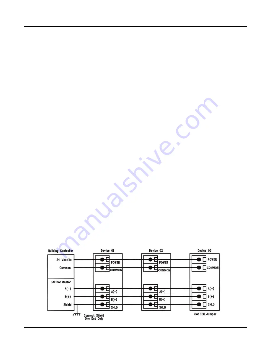
Connect the RS-485 network with twisted shielded pair to the terminals marked
A-
,
B+
and
SHLD
. The positive wire
connects to
B(+)
and the negative wire connects to
A(-)
and the cable shield must be connected to the
SHLD
(shield)
terminal on each device. If the device is installed at either end of the network, an end-of-line (EOL) termination resistor (121
ohm) should be installed in parallel to the A(-) and B(+) terminals.
This device includes a network termination jumper and
will connect the resistor correctly on the pcb. Simply move the pcb jumper to the
EOL
position and no external resistor is
required. The ground wire of the shielded pair should be connected to earth ground at one end of the network. Do not run bus
wiring in the same conduit as line voltage wiring.
A network segment is a single shielded wire loop run between several devices (nodes) in a daisy chain configuration. The
total segment length should be less than 4000 feet (1220 meters) and the maximum number of nodes on one segment is 127
for BACnet or 255 for ModBus. Nodes are any device connected to the loop and include controllers, repeaters and sensors
such as the CO Transmitter but do not include the EOL terminators. To install more devices, or to increase the network
length, repeaters will be required for proper communication. The maximum daisy chain length (segment) depends on
transmission speed (baud rate), wire size and number of nodes. If communication is slow or unreliable, it may be necessary to
wire two daisy chains to the controller with a repeater for each segment.


