Greystone CMD5B1 Series Скачать руководство пользователя страница 4

Carbon Monoxide Transmitter                                                             

Installation Manual 


IN-CMD5B1-01-01  


                  May 2, 2017 


  Page 4 

The sensor must be continuously powered for at least 1/2 hour prior to calibration.  
 
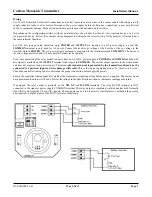
For local display, an ammeter can be placed in series of the output.  Disconnect the signal wire from the OUT terminal of the 
CO sensor.  Connect the + lead of the ammeter to the OUT terminal of the CO sensor and connect the COM lead of the 
ammeter to the removed signal wire.  Set ammeter to porper setting to read a 20 MA signal. 
 
Calibrate the sensor first in clean air with no CO gas present. Simply adjust the ZERO pot on the sensor board until a 4 mA 
output is obtained. 
 
Then attach the gas supply. Turn the regulator on/off knob fully off and attach it to the 250 ppm gas bottle and firmly tighten 
it by hand. Moisten the sponge and squeeze out any excess water. Place the sponge in the cap so that it will not touch the 
sensor but does not plug the hole in the side of the cap. Attach the cap to the fixture over the sensor. Slowly turn the valve 
knob on the regulator to let the gas begin flowing. 
 
The regulator will restrict the flow rate to the specified 200 ml/min and the sponge will ensure the gas is in the right humidity 
range. Wait for 5 minutes and then adjust the SPAN pot on the sensor board until the output reads 250 ppm. Close the valve 
on the tank and take the cap off from the sensor. Calibration is complete. 
 
If the gas cap is too loose on the fixtures, simply place a wrap of electrical tape around the cap to tighten it up. 
 
Once calibration is complete, remove ammeter and reconnect signal wire to OUT terminal of the CO sensor. 


Содержание CMD5B1 Series

Страница 1: ...tion In normal operation the sensor will measure the CO level in the surrounding air and output a proportional value on the 4 20 mA output The CO measurement range is 0 to 300 ppm An optional relay can be used to indicate an alarm condition The trip point for the relay can be programmed to three different settings with an on board jumper If the CO level exceeds the trip point then the relay is act...

Страница 2: ...ll not operate if connected backwards For 3 wire operation of the relay model connect either an AC or DC power supply to POWER and COMMON and the 4 20 mA signal is available on the OUTPUT terminal with respect to COMMON The current output operates in the Active mode and does not require a loop power supply This means the signal current is generated by the transmitter and must not be connected to a...

Страница 3: ...tter using the sensor swap method The device may also be calibrated or verified with CO gas if required This requires a field calibration kit consisting of a bottle of gas 250 ppm CO in air for example a tank pressure regulator with flow restrictor and the necessary tubing with a calibration cap to cover to the sensor Calibration can be done at 20 27 C Verification Verification with gas can be don...

Страница 4: ... and attach it to the 250 ppm gas bottle and firmly tighten it by hand Moisten the sponge and squeeze out any excess water Place the sponge in the cap so that it will not touch the sensor but does not plug the hole in the side of the cap Attach the cap to the fixture over the sensor Slowly turn the valve knob on the regulator to let the gas begin flowing The regulator will restrict the flow rate t...

Страница 5: ...overage 700 m2 7500 ft2 or 15 m 50 ft radius Wiring Connections Screw terminal block 14 to 22 AWG Enclosure 2 8 w x 4 1 h x 1 9 d 71 x 104 x 48 mm 2 Wire Loop Powered Model Power Supply 24 Vdc 20 or 24 Vac 10 non isolated half wave rectified Consumption 20 mA max Output Signal 4 20 mA loop powered Output Drive Capability 550 ohms max 24 Vac dc 3 Wire Relay Model Power Supply 24 Vdc 20 or 24 Vac 10...

Отзывы: