Page 5
PNEUMATIC CONNECTIONS
The two pressure ports on the enclosure are labeled High and Low. The output signal reads a positive
value when the port pressure is higher on the High port than the Low port so ensure these ports are
connected correctly. Use 1/8" to 3/16" ID flexible tubing for the pressure connections. An flexible silicone
tube is recommended. Arrange the tubing to minimize stress on the connections and ensure there
are no kinks in the tubing. For most accurate measurements, do not leave the Low port open to the
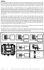
atmosphere, run a return line from the Low port to the vicinity of the point being measured. See Figure 8.
NORMAL OPERATION
During normal mode the device reads the pressure sensor and calculates the pressure value depending
on the device model range and the selected pressure range. The pressure value is then displayed on the
LCD and set as the output value for the analog output. The output value is updated once per second.
The output value may be affected by device settings such as the pressure averaging time. The pressure
averaging setting controls how many readings are averaged to form the output value. For example, if
the pressure averaging value is set to 30 seconds then 30 one-second readings are stored and averaged
to form the output value. The next second will add a new reading and delete the first to form a new 30
second average for output. So the output gets updated every second with a new average reading.
On start-up when the first readings are obtained, the device averages the collected data as necessary
until the required setting is reached. For example, if only 10 readings are available and the pressure
averaging setting is 60 seconds then the output value is calculated as the average of those 10 readings.
The next output value will be an average of 11 readings. This short-averaging will continue until the
averaging setting is reached and then the output value will always be the average of 60 readings. If the
averaging value is changed during operation, this process can be repeated for the new setting.
The averaging value can be set from 1 to 60 seconds via the User Menu.
During normal mode, the device also compares the output pressure value to the alarm setpoints and
takes appropriate action. If the pressure value exceeds the setpoints then an alarm condition is set and
the device will operate in alarm mode. Alarm mode activation is controlled by certain delay times and
user settings described later.
During normal mode, the device also monitor the <UP>, <DOWN> and <MENU> keys and takes
appropriate action. The keys are used for factory configuration, factory calibration and user setup.
The device also monitors a Volt/mA switch and determines the appropriate output scaling. The voltage
span may be set via the User Menu to either 0-5 Vdc or 0-10 Vdc.
ALARM MODE
The relay alarm feature is optional.
The alarm mode has several settings that are controlled by the User Menu. The device has both high and
low alarms with setpoints set via the User Menu. The alarm setpoints can be set over the entire pressure
range with some conditions.
The relay alarm option operates as follows. High and Low setpoints can be set via the User Menu from the
minimum to the maximum pressure of the selected range, either 0-MAX or –MAX to +MAX, depending
on the current setting. When the input pressure exceeds the setpoint for the on delay time, then the relay
contacts will close. When the input pressure decreases below the setpoint for the off delay time then the
relay contacts will open again.
The alarm on and off delay times can be set from 1 to 59 seconds or 1 to 10 minutes via the User Menu. For
an alarm condition to be set the pressure value must exceed the alarm setpoint for more than the alarm on
delay time. For an alarm condition to be reset the pressure value must return to a non-alarm value for more
than the alarm off delay time. When the alarm condition is set the relay output will activate.
The backlight operation defaults to “bL.2” for Auto operation. It can be set to “bL.0”
using <UP> or <DOWN> for Off or “bL.1” for On. Auto means the LCD backlight
only lights when a menu is accessed, off means it never lights and on means it is
always on. The backlight will be On during warm-up and Auto-zero modes.
<MENU>
Press to exit the User Menu and return to normal operation.
12. BACKLIGHT
MENU
IN-GE-UPXXX-01 07/20
Copyright © Greystone Energy Systems, Inc. All Rights Reserved Phone: +1 506 853 3057 Web: www.greystoneenergy.com


