Greyhound GREYHOUND 65761 Скачать руководство пользователя страница 13

SKU 65761 

For technical questions, please call 1-800-444-3353. 

Page 13

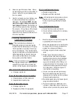
A close-up of this Push Pin (26) is 

shown in FIGURE 3 on page 5. Tilt 

the unit to the vertical position as 

shown in FIGURE 4, and replace 

both the Push Pin (26) and the Hair 

Pin Clip (29) into the vertical posi tion 

hole (See FIGURE 1). Reverse the 

process to return to the horizontal 

position.

Figure 4

Vertical Position

Place 

Log

Here

Base

Start the Engine, following the steps 

3. 

listed in the 

“start procedure”

 sec-

tion of this manual.

Place a log, no more than 25” long 

4. 

and 8” diameter, on the splitter base.

note:

  Maximum diameter of the wood that 

can be split may vary depending on 

the density of the wood.
Move the Directional Valve (58) into 

5. 

the lower position; moving the Slide 

Assembly (3) to split the log.
To stop the advance of the Slide As-

6. 

sembly at any time, move the Direc-

tional Valve to the middle position.
Once the log is split, move the Direc-

7. 

tional Valve to its upper position to 

back the wedge off the log and re-

move the split pieces.
Continue as detailed above until all 

8. 

logs are split.
To prevent accidents, turn off the 

9. 

engine and disconnect its spark plug 

wire after use.  Wait for the engine to 

cool, clean external parts with clean 

cloth, then store the equipment out 

of children’s reach according to the 

Storage instructions in this manual.

transporting the Log splitter

Warning!

iMportant inForMation

This  trailer’s  Hitch  Coupler  MUST 

be  properly  secured  to  the  hitch  ball  of 

the  towing  vehicle.   After  assembly  and 

attachment, pull up and down on the Hitch 

Coupler to make sure the hitch ball is fitting 

snugly in the Hitch Coupler.  

there must 

be  no  play  between  the  hitch  ball  and 

Hitch coupler.

  If there is play, tighten the 

Adjustment Nut until no play is present.  If 

the Adjustment Nut is too tight, the Handle 

will  not  lock.   

carefully  read  and  follow 

the complete instructions in this manual 

BeFore setup or use.

if the coupler is not secured properly, 

the ball could come loose while the trailer 

is in motion, possibly causing property 

damage, serious personaL injurY, 

or deatH.

note:

 This Log Splitter is not road legal 

and should not be conveyed on pub-

lic roads.

When transporting the Log Splitter, 

• 

make sure your hitch (not included) 

is compatible with the Hitch Coupler 

(9). 
Follow all of the safety warn ings for 

• 

towing in the vehicle’s manual. 

Содержание GREYHOUND 65761

Страница 1: ...www harborfreight com Read this material before using this product Failure to do so can result in serious injury Save this manual Copyright 2008 by Harbor Freight Tools All rights reserved No portion of this manual or any artwork contained herein may be reproduced in any shape or form without the express written consent of Harbor Freight Tools Diagrams within this manual may not be drawn proportio...

Страница 2: ...Procedures 14 Engine Oil Change 14 Air Filter Element Maintenance 15 Spark Plug Maintenance 15 Fuel Filter Replacement if equipped 15 Cleaning Maintenance and Lubrication Schedule 16 After Initial 20 Operation Hour Period 16 Every 25 Operation Hours Thereafter 16 Every 50 Operation Hours 16 Every 100 Operation Hours 16 Every 300 Operation Hours 16 Storage 16 Transport Maintenance 17 Troubleshootin...

Страница 3: ...3353 Page 3 Flywheel coil assembly parts list diagram 30 Control system parts list diagram 31 Air cleaner parts list diagram 32 Muffler parts list diagram 33 Muffler parts list diagram 34 Limited 1 year 90 Day warranty 35 Emission Control System Warranty 35 ...

Страница 4: ...ich if not avoided could result in minor or moderate injury NOTICE is used to address practices not related to personal injury CAUTION without the safety alert symbol is used to address practices not related to personal injury WARNING Read all instructions Failure to follow all instructions listed below may result in fire serious injury and or DEATH The warnings and precautions discussed in this m...

Страница 5: ... the vehicle before moving it If the Coupler is not se cured properly the link could come loose while the trailer is in motion possibly causing property damage SERIOUS PERSONAL INJURY or DEATH Never split a log that contains any 6 foreign materials nails for example Never place your hands or body near 7 a hydraulic fluid leak High pressure fluid can be forced under the skin resulting in serious in...

Страница 6: ...20 in accordance with these instructions and in the manner intended for the particular type of equipment taking into account the working conditions and the work to be performed Use of the equipment for operations differ ent from those intended could result in a hazardous situation Do not operate the equipment with 21 known leaks in the engine s fuel sys tem This product contains or when used 22 pr...

Страница 7: ... Maintain labels and nameplates on 5 the equipment These carry impor tant information If unreadable or missing contact Harbor Freight Tools for a replacement Have the equipment serviced by a 6 qualified repair person using only identical replacement parts This will ensure that the safety of the equip ment is maintained Do not attempt any service or maintenance proce dures not explained in this man...

Страница 8: ... intact and undamaged If any parts are missing or broken please call Harbor Freight Tools at the number shown on the cover of this manual as soon as possible Set Up Instructions Read the entire Important Safety Information section at the beginning of this manual including all text under subheadings therein before set up or use of this product To prevent serious injury from accidental starting Turn...

Страница 9: ... turn Insert a Cotter Pin 25 through both the Axle and the Spindle Nut 51 and bend the end of the Pin back to hold it in place Last tap on a Wheel Cap 61 Connecting the Rail Assembly to the Oil Tank Insert the Front Leg Assembly 11 9 into the bracket on the Oil Tank As sembly 10B Insert the remaining Hex Head Bolt 16 through the hole in the middle of the bracket of the Oil Tank Assembly Secure it ...

Страница 10: ...ir Pin Clip 29 Horizontal transport hole Place Log Here Cylinder 1 Hex Head Nut 17 is attached to Hex Head Bolt 16 Vertical position locking hole FIGURE 2 FIGURE 3 Push Pin 26 Hydraulic Oil Fill Plug 37 with air inlet hole Close up of Push Pin 26 securing the Front Leg Assembly 11 to the bracket on the Oil Tank Assembly 10B Second Push Pin 26 secures Rail Assembly 2 and is removed for vertical log...

Страница 11: ...ntil the oil level is full Oil type 32 F or above SAE 10W30 Below 32 F SAE 5W 30 Replace the Oil Fill Cap 3 CAUTION Do not run the engine with too little or too much oil The engine will be permanently damaged Checking and Filling Fuel WARNING To prevent serious injury from fire Fill the fuel tank in a well venti lated area away from ignition sourc es Do not smoke To fill the Fuel Tank first wipe o...

Страница 12: ...peat as necessary until the engine starts After the engine starts and warms 5 up slowly move the choke lever to its RUN position IMPORTANT Allow the engine to run 6 at no load until warm 1 5 minutes Break in Period Breaking in the engine will help to 1 ensure proper equipment and engine operation and will extend the en gine s lifespan The warranty is void if the engine is not broken in properly Th...

Страница 13: ...plit To prevent accidents turn off the 9 engine and disconnect its spark plug wire after use Wait for the engine to cool clean external parts with clean cloth then store the equipment out of children s reach according to the Storage instructions in this manual Transporting the Log Splitter WARNING IMPORTANT INFORMATION This trailer s Hitch Coupler MUST be properly secured to the hitch ball of the ...

Страница 14: ...and Rail Assembly in the horizontal position Cover the air inlet hole on the Plug during transport Pull up and down on the Hitch Cou 10 pler to make sure the hitch ball is fitting snugly in the Hitch Coupler There should be no play between the hitch ball and Hitch Coupler If there is play tighten the Adjustment Nut until no play is present If the Adjust ment Nut is too tight the Handle will not lo...

Страница 15: ...ury from equipment failure Do not use damaged equipment If abnormal noise vibration or excess smoking occurs have the problem corrected before further use Maintenance Procedures Many maintenance procedures including those not detailed in this manual will need to be performed by a qualified technician for safety If you have any doubts about your ability to safely service the equipment or engine hav...

Страница 16: ...d spark plug Using a spark plug wrench remove 2 the spark plug Inspect the spark plug 3 If the electrode is oily clean it using a clean dry rag If the electrode has deposits on it polish it using emery paper If the white insulator is cracked or chipped the spark plug needs to be replaced When installing a new spark plug ad 4 just the plug s gap to the specification on the Technical specification c...

Страница 17: ... Every 25 Operation Hours Thereafter Clean replace air filter element a Inspect clean spark plug b Every 50 Operation Hours Change engine oil a Replace fuel filter if equipped b Every 100 Operation Hours Replace spark plug a Replace air filter element b Note All maintenance procedures sched uled for 25 50 and 100 operation hours should be performed at least yearly Every 300 Operation Hours Clean f...

Страница 18: ...soline has been sitting beyond the fuel stabilizer s recommended time period or if the engine does not start properly Transport Maintenance BEFORE 1 transport check the Tires for wear and proper inflation 60 PSI Prior to Transport and at 500 MILE in 2 tervals during trips check and tighten the Tire Lug Nuts Torque from 85 to 90 ft lb EVERY 2 000 TO 3 000 MILES 3 of Travel lubricate the Hub Assembl...

Страница 19: ...tall spark plug and set choke to start position Ignition spark Related Spark plug wire not connected 1 securely Spark plug electrode wet or dirty 2 Incorrect spark plug gap 3 Spark plug wire or spark plug 4 broken Incorrect spark timing or faulty 5 ignition system Ignition spark Related Connect spark plug wire properly 1 Clean spark plug 2 Correct spark plug gap 3 Replace spark plug wire and or 4 ...

Страница 20: ...asoline Test replace fuel tank cap 3 Properly adjust idle speed 4 Have qualified technician diagnose 5 and service engine Engine knocks Old or low quality gasoline 1 Engine overloaded 2 Incorrect spark timing deposit 3 buildup worn engine or other mechanical problems Fill fuel tank with fresh 89 octane 1 unleaded gasoline Do not exceed equipment s load 2 rating Have qualified technician diagnose 3...

Страница 21: ...y 1 12 Hex Head Bolt 1 2 x1 3 4 2 13 Hex Nut 1 2 2 14 Hex Head Nut 3 8 3 15 Washer 1 2 2 16 Hex Head Bolt 9 16 x1 1 4 2 17 Hex Nut 9 16 2 18 Washer 1 19 Hex Head Bolt 5 16 x2 3 4 1 20 Hex Head Nut 3 8 1 21 O Ring 1 22 Hex Head Bolt 1 2 x1 3 4 4 23 Hex Nut 5 16 4 24 Spring Washer 5 16 8 25 Cotter Pin 2 26 Push Pin 2 27 Clevis Pin 1 28 Hair Pin Clip 2 29 Hair Pin Clip 2 5 2 30 Slide Holder 1 31 Hydr...

Страница 22: ...SKU 65761 For technical questions please call 1 800 444 3353 Page 22 ASSEMBLY DIAGRAM ...

Страница 23: ...g Tube 1 8B Spark Plug 1 9B Cylinder Gasket 1 10B Muffler Gasket 1 11B Pin 2 12B Bolt 6x14 4 13B Bolt 8x55 4 14B Intake Bolt 2 15B Exhaust Bolt 2 16B Intake Valve Seat 1 17B Exhaust Valve Seat 1 18B Cylinder Head 1 Note When ordering replacement parts from this diagram the B suffix must be includ ed in order to get the correct part Note Some parts are listed and shown for illustration purposes onl...

Страница 24: ...in Plug Bolt 2 10C Washer 2 11C Washer 2 12C Clip 1 13C Ball Bearing 1 14C Oil Seal 1 15C O ring 1 16C Nut 1 17C Washer 1 Part Description Qty 18C R pin 1 19C Bolt 6x12 3 20C Shaft 1 21C Governor Assembly 1 22C Oil Alarm 1 23C Bolt 1 Note When ordering replacement parts from this diagram the C suffix must be includ ed in order to get the correct part Note Some parts are listed and shown for illust...

Страница 25: ...tick 1 3D Packing 2 4D Cover 1 5D Oil Seal 1 6D Bearing 1 7D Pin 2 8D Oil Filler Cap 1 9D Packing Case Cover 1 10D Oil Fill Assembly 1 11D Cap Assembly 1 Note When ordering replacement parts from this diagram use the suffix D Note Some parts are listed and shown for illustration purposes only and are not avail able individually as replacement parts ...

Страница 26: ...ssembly 1 6E Bolt 2 7E Clip 2 8E Timing Gear 1 9E Gear 1 10E Crankshaft 1 11E First Ring 1 12E Second Ring 1 13E Oil Ring 2 14E Bushing Ring 1 15E Connecting Rod 1 16E Connecting Rod Cover 1 17E Key 1 Note When ordering replacement parts from this diagram use the suffix E Note Some parts are listed and shown for illustration purposes only and are not avail able individually as replacement parts ...

Страница 27: ... Valve 2 11F Valve Spring Retainer 2 12F Valve Spring 2 13F Guide Seal 1 Part Description Qty 14F Camshaft Assembly 1 15F Reducer Pin 1 16F Reducer 1 17F Matching Block Pin 2 18F Matching Block 1 19F Flying Block Pin 1 20F Spring Pin 1 21F Flying Block Spring 1 22F Flying Block 1 23F Camshaft 1 24F Exhaust Valve 1 25F Intake Valve 1 Note When ordering replacement parts from this diagram use the su...

Страница 28: ...ring 2 7G Recoil Starter Reel 1 8G Recoil Starter Spring 1 9G Recoil Starter Knob 1 10G Fan Cover 1 11G Rope 1 12G Bolt 6x8 3 13G Bolt 6x10 4 14G Fan Cover 1 15G Switch Assembly 1 16G Recoil Starter 1 17G Fan Cover 1 18G Stop Switch Assembly 1 Note When ordering replacement parts from this diagram use the suffix G Note Some parts are listed and shown for illustration purposes only and are not avai...

Страница 29: ...am Part Description Qty 1H Bolt 6x20 1 2H Side Plate 1 3H Bolt 6x8 2 4H Shroud 1 5H Side Plate 1 6H Grommet 1 Note When ordering replacement parts from this diagram use the suffix H Note Some parts are listed and shown for illustration purposes only and are not avail able individually as replacement parts ...

Страница 30: ...Gasket Bolt 1 12J Bolt 1 13J Drain Bolt 1 14J Drain Bolt Gasket 1 15J Fuel Strainer Cup 1 16J Fuel Strainer Cup Packing 1 17J Fuel Packing 1 18J Lever 1 Part Description Qty 19J Lever Spring 1 20J Setting Plate 1 21J Screw 3x8 2 22J Jet Set 1 23J Pilot Jet Set 1 24J Choke Lever Assembly 1 25J Choke Lever 1 26J Choke Lever Pin 1 27J Choke Set 1 28J Screw 1 29J Screw Spring 1 30J Throttle Stop Screw...

Страница 31: ...1 4K Stop Switch Cord 1 5K Bolt 6x30 2 6K Flywheel Cover 1 7K Charge Coil Assembly 1 8K Cooling Fan 1 9K Starter Pulley 1 10K Nut 1 11K Flywheel 1 12K Charge Coil 1 13K Bolt 6x35 2 14K Cord Clamp 1 15K Bolt 6x8 1 Note When ordering replacement parts from this diagram use the suffix K Note Some parts are listed and shown for illustration purposes only and are not avail able individually as replacem...

Страница 32: ...y 1 9M Nut 1 10M Fixing Plate 1 11M Washer 1 Part Description Qty 12M Washer 1 13M Retainer Assembly 1 14M Spring 1 15M Screw M5x35 16M Cable Return Spring 1 17M Control Handle 1 18M Screw M5x25 1 19M Back Plate 1 20M Screw M4x6 1 21M Locking Ring 1 22M Clip 1 Note When ordering replacement parts from this diagram use the suffix M Note Some parts are listed and shown for illustration purposes only...

Страница 33: ...x20 1 7N Nut 6mm 2 8N Nut 2 9N Air Cleaner Cover 1 Part Description Qty 10N Air Cleaner Element Assembly 1 11N Grommet 1 12N Outer Filter 1 13N Element 1 14N Noise Silencer 1 15N Air Cleaner Assembly 1 16N Cover 1 17N Screw 2 Note When ordering replacement parts from this diagram use the suffix N Note Some parts are listed and shown for illustration purposes only and are not avail able individuall...

Страница 34: ...iption Qty 1P Muffler 1 2P Nut 8mm 1 3P Muffler Cover 1 4P Screw 5x8 4 5P Muffler Assembly 1 6P Muffler Case 1 Note When ordering replacement parts from this diagram use the suffix P Note Some parts are listed and shown for illustration purposes only and are not avail able individually as replacement parts ...

Страница 35: ...iption Qty 1P Muffler 1 2P Nut 8mm 1 3P Muffler Cover 1 4P Screw 5x8 4 5P Muffler Assembly 1 6P Muffler Case 1 Note When ordering replacement parts from this diagram use the suffix P Note Some parts are listed and shown for illustration purposes only and are not avail able individually as replacement parts ...

Страница 36: ...epaired products at our expense but if we determine there is no defect or that the defect resulted from causes not within the scope of our warran ty then you must bear the cost of returning the product This warranty gives you specific legal rights and you may also have other rights which vary from state to state 3491 Mission Oaks Blvd PO Box 6009 Camarillo CA 93011 800 444 3353 Emission Control Sy...

Страница 37: ...e filed in accordance with the provi sions of the HFT warranty policy explained in the box at the top of the previous page HFT shall not be liable for any loss of use of the engine for any alternative usage for any damage to goods loss of time or inconvenience Warranty coverage shall also be excluded for any part which fails malfunctions or is damaged due to failure to follow the maintenance and o...

Отзывы: