


SKU 65761
For technical questions, please call 1-800-444-3353.
Page 10
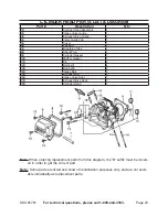
Hex Head Nut (17) is attached to Hex Head Bolt (16)
Rail Assembly
(2)
Hydraulic Oil Tank (10B)
Oil Plug (37)
with air inlet hole
Wheel Cap (61)
Figure 1
Safety Chain
with Hook (4)
Hitch
Coupler (9)
Front Leg Assembly (11)
Oil Drain Plug
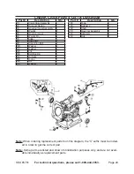
Push Pin (26) and
Hair Pin Clip (29
)
Horizontal transport hole
Place Log Here
Cylinder (1)
Hex Head Nut (17) is
attached to Hex Head
Bolt (16)
Vertical position
locking hole
Figure 2
Figure 3
Push Pin (26)
Hydraulic Oil Fill Plug (37)
with air inlet ho
le
Close-up of Push Pin (26) securing the
Front Leg Assembly (11) to the bracket
on the Oil Tank Assembly (10B).
Second Push Pin (26) secures
Rail Assembly (2), and is removed
for vertical log splitting.
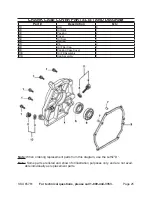
Horizontal transport hole
Air Inlet Hole
Slide Assembly (3)
Base
Vertical Position Hole
Push Pin (26)