6
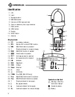
Identification
1. Jaw
2. Lever
3. Backlight button
4. MIN MAX button
5. Common (COM) input terminal
6. Volts or resistance (V-
Ω
) input terminal
7. PEAK button
8. ZERO button
9. Display
10. HOLD button
11. Selector
Display Icons
12.
Low battery indicator
13. REL
Status of DC current ZERO function
14. MIN
MIN Hold function is enabled
15.
–
Polarity indicator for numeric display
16. MAX
MAX Hold function is enabled
17.
Hold function is enabled
18.
DC measurement is selected
19.
AC measurement is selected
20. kHz
Kilohertz
21. MHz
Megahertz
22. Volts
Voltage
23. Amps
Amperes
24.
Ohms
25.
Continuity
26. TRMS True RMS (CM-1550 only)
27. P
MAX
MAX PEAK Hold function is enabled.
28. P
MIN
MIN PEAK Hold function is enabled.
29.
–
Polarity indicator for bar graph
30.
Bar graph element
31.
Overload indicator for bar graph
32.
OL.
Overload indicator for numeric display
Symbols on the Unit
Warning—Read the
instruction manual
Double insulation
Battery
1
2
3
4
5
10
11
9
8
7
6
12
13–14
15
16
17
26–28
18–25
30
29
31
32
Содержание CM-1500
Страница 12: ...12 Typical Measurements Continuity Check...
Страница 31: ...CM 1500 CM 1550 31 Mesures types V rification de la continuit...
Страница 48: ...48 Misure tipiche Controllo della continuit...
Страница 66: ...66 Typische Messungen Durchgangspr fung...
Страница 84: ...84 Mediciones m s comunes Verificaci n de continuidad...
Страница 102: ...102 Medi es mais comuns Teste de continuidade...
Страница 120: ...120 Typische metingen Continu teitscontrole...
Страница 127: ...CM 1500 CM 1550 127...


