background image

Greenlee / A Textron Company

8

4455 Boeing Dr. • Rockford, IL 61109-2988 USA • 815-397-7070

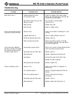
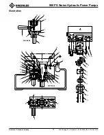
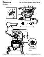
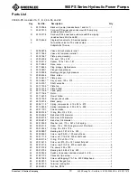
960 PS Series Hydraulic Power Pumps

Operation

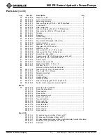
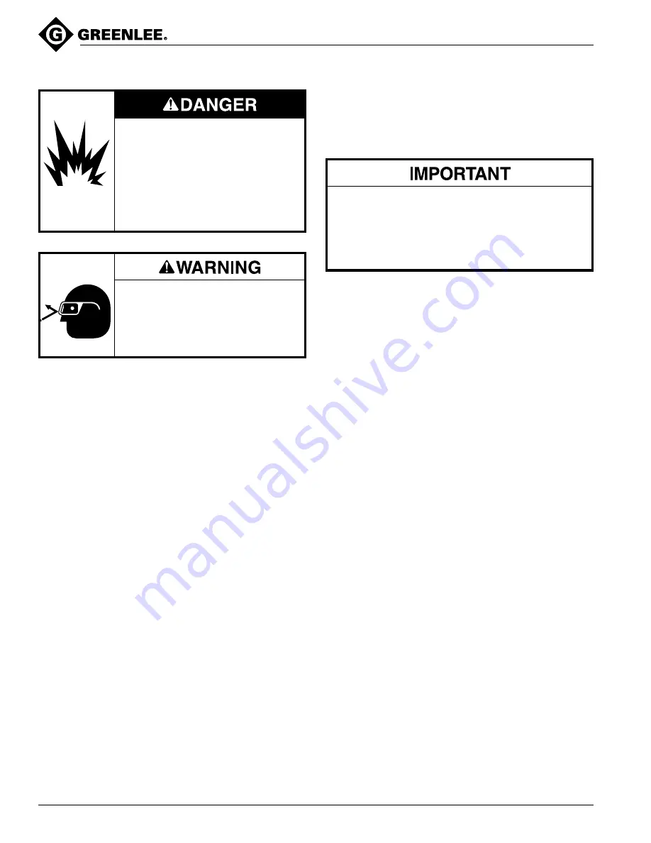
Do not use this pump in a hazardous
environment. Hazards include
flammable liquids, gases, or other
materials. Using this pump in a
hazardous environment can result in
a fire or explosion.

Failure to observe these warnings
will result in severe injury or death.

Wear eye protection when operating
or servicing this tool.

Failure to wear eye protection can
result in serious eye injury from
flying debris or hydraulic oil.

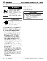
Procedure for depressurizing the hydraulic system:

1.

Disconnect the pump from the power source.

2.

Rotate the release lever clockwise.

3.

Disconnect the hose slowly to release any
trapped pressure.

Changing Accessories

Before changing the hydraulic accessory that is
connected to the pump, follow this procedure for
depressurizing the system.

Note: Starting the motor without a tool attached to the
pump will cause the pump to immediately build an
internal pressure of 689.5 bar (10,000 psi).
If this happens, shut off the pump and turn the valve
lever clockwise to release the hydraulic pressure.

1.

Move release valve lever clockwise.

2.

Check reservoir oil level. The oil level should be
within 13 mm (1/2") of the top of the reservoir.
If oil level is too low, refer to “Adding Oil” under
“Maintenance and Service” in this manual.

3.

Turn the dipstick two turns counterclockwise.
Note: Operating the pump without loosening the
dipstick will result in poor pump performance.

4.

Connect the pump to an appropriate power supply.

5.

Start motor and allow pump to idle for a few minutes.
This will allow the hydraulic fluid to work through the
system and prime the pump.

6.

Stop the motor. Turn the lever counterclockwise.

7.

Start the motor to advance the hydraulic ram. When
finished, stop the motor. Turn the lever clockwise to
release the pressure.
Note: Starting the pump while the lever is in the
clockwise position may cause the ram to extend.

Turning the lever counterclockwise while the pump is
running may release the pressure.

8.

During periods of heavy use, occasionally stop the
pump and check the oil temperature. The recom-
mended operating temperature is 38 

°

C to 50 

°

C

(100 

°

F to 125 

°

F).

9.

Tighten the dipstick.

Содержание 960-PS

Страница 1: ...Greenlee Textron IM 1007 REV 15 12 02 Read and understand all of the instructions and safety information in this manual before operating or servicing this tool 960 PS Series Hydraulic Power Pumps Beg...

Страница 2: ...lly powered two stage pumps that develop a maximum of 689 5 bar 10 000 psi The pumps are intended to provide hydraulic power for an accessory with a single acting ram hydraulic cylinder such as a Gree...

Страница 3: ...can develop which can cause a component failure Nearby personnel can be injured by flying components and hydraulic oil Failure to observe this warning will result in severe injury or death Do not use...

Страница 4: ...tings for wear or damage Replace worn damaged or missing components with Greenlee replacement parts Worn or damaged components can fail resulting in injury Failure to observe this warning can result i...

Страница 5: ...13 7 bar to 689 5 bar 6000 psi to 10 000 psi intermittent use this limitation is for motor protection only Power Source 115 VAC 60 Hz Dimensions Length 30 5 cm 12 Width 26 75 cm 10 5 Height 65 cm 25 5...

Страница 6: ...ngs can result in severe injury or death This tool must be grounded In the event of a malfunc tion or breakdown an electrical ground provides a path of least resistance for the electric current This p...

Страница 7: ...with a NEMA 6 15 plug Solid state relay Part No 918 6403 8 motor switch and all other components are suitable for 230 volt operation Note Greenlee will not be held liable for injuries or damage resul...

Страница 8: ...9 5 bar 10 000 psi If this happens shut off the pump and turn the valve lever clockwise to release the hydraulic pressure 1 Move release valve lever clockwise 2 Check reservoir oil level The oil level...

Страница 9: ...aulic cylinder of the accessory to a full stroke and repeat several times Stop pump and rotate valve clockwise to retract ram As the ram retracts the oil in the hose will return to the reservoir in th...

Страница 10: ...ief valve Replace valve 2 Faulty low pressure system Repair low pressure system Purchase Vane Repair Kit Refer to the repair kits at the end of the parts list Pump develops substantial Low pressure sy...

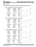
Страница 11: ...IL 61109 2988 USA 815 397 7070 960 PS Series Hydraulic Power Pumps Illustration 22 37 26 20 4 25 19 40 1 B A B B 2 SECTION BB 38 28 4 23 36 29 26 7 33 9 8 22 41 13 3 34 5 32 6 35 30 10 24 18 15 12 17...

Страница 12: ...D 22 59 960 SERIES 76 74 66 77 75 A 67 56 54 64 53 62 61 69 81 83 82 84 94 52 59 60 63 57 58 65 55 56 BLACK BLACK WHITE 2 3 WHITE GREEN 1 4 72 70 80 92 1 8 ALLEN WRENCH Item 92 is threaded onto Item...

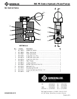
Страница 13: ...35 6 Vane pump 4 17 501 7136 4 Rotor 1 18 501 7467 3 Dowel hollow 1 19 501 8195 5 Plunger check valve 1 20 501 8237 4 Block pump 1 22 500 6111 9 Spring compression 219 x 281 x 875 1 23 501 4865 6 Spri...

Страница 14: ...1269 3 Screw set 1 4 20 x 250 socket head 1 81 905 1428 9 Caster swivel 4 82 905 2836 0 Washer shakeproof 3 8 8 83 905 1434 3 Washer flat 13 32 x 13 16 x 1 16 4 84 905 1435 1 Nut hex 3 8 16 4 85 Motor...

Страница 15: ...6 0 5KC48SG573T Motor 1 918 5466 0 5KC48SG952T Motor 1 918 5701 5 111A277P1 Capacitor 1 918 5356 7 111B277AAP1 Cover cap 1 918 5726 0 114A882AAG7 Fan 1 918 5361 3 114C922AAP1 Canopy cover fan 1 Greenl...

Страница 16: ...ick 3 8 2 9 905 0505 0 Washer lock 5 16 x 9 16 x 1 16 2 10 905 0714 2 Ball steel 7 16 1 11 905 0747 9 Ring backup 3 8 x 9 16 1 12 905 1172 7 Screw hex head cap 5 16 24 x 1 1 2 2 13 905 0431 3 Knob 1 K...

Отзывы: