Greenheck Steel Airfoil Blades FSD-331 Скачать руководство пользователя страница 6

5

3

/

8

"

5"

Right hand drive is shown  

Left hand drive available upon request

LH

RH

A

Sleeve Length

Varies

6"

3

3

/

4

"

11/2" max.

B*

S

T*

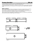
damper sleeve dimensional data

The drawings below and corresponding table show the position of the FSD-331 damper when mounted in a factory sleeve. 

The standard mounting locations provide enough space for the mounting of actuators, controls and allow space for 

installation of retaining angles and duct connections.

The standard location of a damper mounted in a factory sleeve ("A" dimension) is shown below. The damper can be 

positioned at other locations within a range of 6 in. (152mm) to 12 in. (305mm) for the "A" dimension.

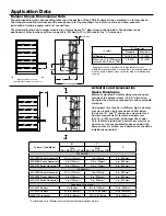
Actuators and Accessories 

space envelopes

Externally mounted actuators always require space 

outside of the damper sleeve. The “S” dimension 

illustrates the clearance required for various available 

actuators.

On dampers less than 18 in. (457mm) high, actuators 

may also require clearances above and/or below 

the sleeve. “B” and “T” dimensions are 

worst

 case 

clearance requirements for some dampers less 

than 18 in. (457 mm) high. All damper sizes under 

18 in. (457mm) high do not require these worst case 

clearances. If space availability above or below the 

damper sleeve is limited, each damper size should be 

individually evaluated. 

Application data

5

3

/

8

"

5"

Right hand drive is shown  

Left hand drive available upon request

LH

RH

A

Sleeve Length

Varies

6"

3

3

/

4

"

11/2" max.

B*

S

T*

*With the exception of dampers 10 in. high (254mm) or less. 

NOTE: Entire damper frame is not required to be installed within the 

wall. The damper blades, when closed should be contained within 

the wall.

in. (mm)

"A" Dimension

Standard

Maximum

All Dampers*

7 3/16 (183)

12 (305)

When H is 11 in. (279mm) or 

less with OCI, RRL, or TOR

12 (305)

12 (305)

* For dampers 18 in. (457mm) or more in height these dimensions are 0 in. .

Actuator Type/Model

B*

T*

S

With 

RRL, RRL/OCI, or TOR

With

RRL, RRL/OCI, or TOR

120 Volt AC

ML-4XXX Series Honeywell

5¼ in. (133mm)

¾ in.(19mm)

6 in. (152mm)

MS-4XXX Series Honeywell

6 in. (152mm)

3/8 in. (10mm)

6 in. (152mm)

MS-4120 Series Honeywell

6 in. (152mm)

3/8 in. (10mm)

6 in. (152mm)

24 Volt AC

ML-8XXX Series Honeywell

5¼ in. (133mm)

¾ in.(19mm)

6 in. (152mm)

MS-8XXX Series Honeywell

6 in. (152mm)

6 in. (152mm)

6 in. (152mm)

MS-8120 Series Honeywell

6 in. (152mm)

6 in. (152mm)

6 in. (152mm)

Pneumatic (25 psi min.)

331-4551 Powers

1 in. (25mm)

6¼ in. (159mm)

6½ in. (165mm)

331-2976 Powers

2 3/8 in. (60mm)

12 1/8 in. (308mm)

9¼ in. (235mm)

MK2-7121 Invensys

3 3/4 in. (95mm)

16½ in. (419mm)

10 in. (254mm)

Содержание Steel Airfoil Blades FSD-331

Страница 1: ...tures RRL OCI Open closed indication switches 165ºF 74 C 212ºF 100 C 250ºF 121 C 350ºF 177 C RRL s available TOR remote override closure allows damper to perform smoke management functions during a fire emergency Electric or pneumatic actuators to accomplish smoke management and system functions POC retaining angles Smoke detectors Momentary Switch Transitions R C O PRV pneumatic relief valve Secu...

Страница 2: ...strates a fully ducted damper This configuration has the lowest pressure drop of the three test configurations because entrance and exit losses are minimized by straight duct runs upstream and downstream of the damper Figure 5 2 Illustrates a ducted damper exhausting air into an open area This configuration has a lower pressure drop than Figure 5 5 because entrance losses are minimized by a straig...

Страница 3: ...500 0 34 2500 0 34 2500 0 33 2500 0 51 3000 1 04 3000 0 49 3000 0 49 3000 0 48 3000 0 74 3500 1 41 3500 0 67 3500 0 67 3500 0 65 3500 1 00 4000 1 84 4000 0 87 4000 0 88 4000 0 85 4000 1 31 12in X 48 in 305mm x 1219mm 48 in x 12 in 1219mm x 305mm 24 in x 24 in 610mm x 610mm 36in x 36 in 914mm x 914mm 12 in x 12 in 305mm x 305mm R Greenheck Fan Corporation certifies that the model FSD 331 shown here...

Страница 4: ...00 0 21 3000 0 24 3000 0 42 3500 0 73 3500 0 32 3500 0 29 3500 0 33 3500 0 57 4000 0 95 4000 0 42 4000 0 38 4000 0 43 4000 0 74 24 in x 24 in 610mm x 610mm 36in x 36 in 914mm x 914mm 12in X 48 in 305mm x 1219mm 48 in x 12 in 1219mm x 305mm 12 in x 12 in 305mm x 305mm 1 2 x 1 2 4 8 x 1 2 1 2 x 4 8 24x24 3 6 x 3 6 Sizes are in inches R Greenheck Fan Corporation certifies that the model FSD 331 shown...

Страница 5: ...0 81 2500 0 75 2500 0 77 2500 0 89 3000 1 68 3000 1 17 3000 1 08 3000 1 11 3000 1 28 3500 2 29 3500 1 60 3500 1 48 3500 1 51 3500 1 75 4000 2 09 4000 2 14 4000 1 93 4000 1 97 4000 2 29 24 in x 24 in 610mm x 610mm 36in x 36 in 914mm x 914mm 12in X 48 in 305mm x 1219mm 48 in x 12 in 1219mm x 305mm 12 in x 12 in 305mm x 305mm R Greenheck Fan Corporation certifies that the model FSD 331 shown herein i...

Страница 6: ...ire these worst case clearances If space availability above or below the damper sleeve is limited each damper size should be individually evaluated Application Data 53 8 5 Right hand drive is shown Left hand drive available upon request LH RH A Sleeve Length Varies 6 33 4 11 2 max B S T With the exception of dampers 10 in high 254mm or less NOTE Entire damper frame is not required to be installed ...

Страница 7: ... designed to inflate and provide a tighter seal against leakage as pressure on either side of the damper increases Jamb seals shall be stainless steel compression type Blades shall be completely symmetrical relative to their axle pivot point presenting identical resistance to airflow in either direction or pressure on either side of the damper Damper must be rated for mounting vertically with blad...

Отзывы: