background image

1

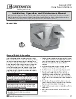
Energy Recovery Ventilator

Installation, Operation and Maintenance Manual

Please read and save these instructions. Read carefully before attempting to assemble, install, operate or maintain the 
product described. Protect yourself and others by observing all safety information. Failure to comply with instructions 
could result in personal injury and/or property damage! Retain instructions for future reference.

®

Document 473007

Energy Recovery Ventilators

Only qualified personnel should install this system. 
Personnel should have a clear understanding of these 
instructions and should be aware of general safety 
precautions. Improper installation can result in electric 
shock, possible injury due to coming in contact with 
moving parts, as well as other potential hazards. 
Other considerations may be required if high winds 
or seismic activity are present. If more information 
is needed, contact a licensed professional engineer 
before moving forward.

1.  Follow all local electrical and safety codes, as well 

as the National Electrical Code (NEC), the National 
Fire Protection Agency (NFPA), where applicable. 
Follow the Canadian Electric Code (CEC) in 
Canada.

2.  All moving parts must be free to rotate without 

striking or rubbing any stationary objects.

3.  Unit must be securely and adequately grounded.

4.  Do not spin fan wheel faster than maximum 

cataloged fan RPM. Adjustments to fan speed 
significantly effects motor load. If the fan RPM is 
changed, the motor current should be checked to 
make sure it is not exceeding the motor nameplate 
amps.

5.  Do not allow the power cable to kink or come in 

contact with oil, grease, hot surfaces or chemicals. 
Replace cord immediately if damaged.

6.  Verify that the power source is compatible with the 

equipment.

7.  Never open access doors to the unit while it is 

running.

General Safety Information

DANGER

Always disconnect power before working on or near 
this equipment. Lock and tag the disconnect switch 
or breaker to prevent accidental power up.

CAUTION

When servicing the unit, the internal components 
may be hot enough to cause pain or injury. Allow 
time for cooling before servicing.

CAUTION

Precaution should be taken in explosive 
atmospheres.

Model ERV

e

Содержание ERVe

Страница 1: ...codes as well as the National Electrical Code NEC the National Fire Protection Agency NFPA where applicable Follow the Canadian Electric Code CEC in Canada 2 All moving parts must be free to rotate wi...

Страница 2: ...ve been received If any items are missing report shortages to your local representative to arrange for obtaining missing parts Sometimes it is not possible that all items for the unit be shipped toget...

Страница 3: ...ct Overview The ERVe brings in fresh outdoor air and removes stale exhaust air Prior to discharging the exhaust air the energy recovery wheel transfers energy from the exhaust air to the outdoor air a...

Страница 4: ...4 21 8 23 9 All dimensions are in inches Door handles hinges and other protrusions are not included in the dimensions above Dimensions are rounded up to the nearest 1 inch Duct Dimensions Unit Size A...

Страница 5: ...of a clearance of one inch must be maintained between the outside edges of the duct and combustible material in accordance with NFPA Standard 90A Unit Size A B Approx Weight lbs ERVe 20 22 37 825 ERVe...

Страница 6: ...ration it is important that the installation be level Shim as required to level 3 Install Ductwork Installation of all ducts should be done in accordance with SMACNA and AMCA guidelines Duct adapter p...

Страница 7: ...raight duct lengths were calculated based on 100 effective duct length requirements as prescribed in AMCA Publication 201 Calculated values have been rounded up to nearest foot Ductwork Connections Ex...

Страница 8: ...rating plate Voltage Imbalance In a 3 phase system excessive voltage imbalance between phases will cause motors to overheat and eventually fail Maximum allowable imbalance is 2 To determine voltage i...

Страница 9: ...gauge Control wires should not be run inside the same conduit as that carrying the supply power Make sure that field supplied conduit does not interfere with access panel operation If wire resistance...

Страница 10: ...R EXHAUST DIRTY FILTER SWITCH SUPPLY DIRTY FILTER SWITCH HOT COMMON Dirty Filter Indicator powered by others A W1 12 7 6 Y2 Y1 G C R UNIT ON OFF COOL STAGE 1 ECONOMIZER COOL STAGE 2 UNOCCUPIED RECIRCU...

Страница 11: ...modes are available 1 Stopping the wheel 2 Modulating the wheel Stopping the wheel A field supplied call for cool Y1 is required De energizing the wheel is accomplished one of three ways 1 The outdoor...

Страница 12: ...ill run at full speed If the outdoor air temperature is less than 5 F AND the pressure differential is greater than the set point the wheel will run at reduced speed until the pressure differential fa...

Страница 13: ...______ Start Up Company _______________________________ Phone Number _______________________________ Pre Start Up Checklist check as items are completed Disconnect and lock out all power switches Remo...

Страница 14: ...es No Wheel Rotation Sensor Yes No N A Yes No OA Dirty Filter Sensor Yes No N A Yes No EA Dirty Filter Sensor Yes No N A Yes No CO2 Sensor Yes No N A Yes No Service Outlet Yes No N A Yes No Remote Con...

Страница 15: ...fter adjustment Check pulleys and belts for proper alignment to avoid unnecessary belt wear noise vibration and power loss Motor and drive shafts must be parallel and pulleys in line see diagrams in t...

Страница 16: ...s door and apply power Observe by opening door slightly remove filters if necessary to view wheel the wheel should rotate freely at about 20 40 RPM Energy Recovery Wheel The ERVe models contain a tota...

Страница 17: ...arameter value 6 Press the button to increase change the displayed parameter value 7 Press enter to accept the displayed value and store it in non volatile RAM 8 CHANGE STORED displays 9 Press enter t...

Страница 18: ...Hz TO CHANGE THE FACTORY SET Hz CHANGE THE FOLLOWING PARAMETERS PARAMETER A1 01 CHANGE TO 2 PARAMETER d1 02 FOR NEW 40Hz SETTING PARAMETER d1 01 FOR NEW 60Hz SETTING PARAMETER d1 03 FOR NEW 30Hz SETTI...

Страница 19: ...ers command the VFD to run at multiple speed settings Open Drive runs at 60 Hz SC to S4 Drive runs at 40 Hz SC to S5 Drive runs at 30 Hz CO2 Sensor Set Point Control A carbon dioxide sensor is provide...

Страница 20: ...ecel Time 600 C4 01 Torque Gain 0 6 C6 02 Carrier Frequency 2 D2 01 Ref Upper Limit 40 or 50 D2 02 Ref Lower Limit 5 E2 01 Motor Rated FLA Motor FLA E2 03 Motor No Load Current Must be less than FLA H...

Страница 21: ...periodically thereafter Fan Motors Motor maintenance is generally limited to cleaning and lubrication Cleaning should be limited to exterior surfaces only Removing dust and grease buildup on the moto...

Страница 22: ...ency of cleaning depends upon the cleanliness of the incoming air These filters should be cleaned prior to start up Clean filters by rinsing with a mild detergent in warm water Internal Filter Mainten...

Страница 23: ...does not affect its performance Thoroughly spray wheel matrix with household cleaner such as Fantastik or equivalent Gently rinse with warm water and using a soft brush remove any heavier accumulatio...

Страница 24: ...ult the factory Clearing Alarms Once the alarm has been identified and the cause has been removed e g replaced faulty sensor the alarm can be cleared from the display To clear an alarm perform the fol...

Страница 25: ...lease determine the following information Airflow problems can often be tied back to improper ductwork installation Be sure to install ductwork in accordance with SMACNA and AMCA guidelines Unit 1 Uni...

Страница 26: ...pressures are higher or lower than design If higher ductwork should be improved If lower fan rpm should be lower Blower rotation is incorrect Check rotation and reverse if necessary Motor voltage inc...

Страница 27: ...gy wheel runs intermittently Wheel motor overloads are tripping due to rubbing between wheel and air seals Recheck air seals make sure they are not too tight See Energy Recovery Wheel under Unit Start...

Страница 28: ..._________________________________________ _________________________________________________ _________________________________________________ _________________________________________________ ________...

Отзывы: