


4
Grease Grabber™ Power Play Kitchen Exhaust Pollution Control System
Installation
Remote Mounted Detergent Dispenser
A 55 gallon remote mounted detergent dispenser
is included as part of the electrostatic collector
self-wash system. Included as part of the 55 gallon
dispenser assembly is a solenoid valve, pressure
gauge, ball valve, y strainer, and backflow preventer.
The detergent dispenser must be mounted indoors
on a solid, level foundation, as close to the cabinet
assembly as possible, and in a freeze protected
location accessible to maintenance personnel. The
1/2 inch line from the detergent dispenser must be
connected to the water supply line within 5 feet of
the precipitator. Refer to the PLUMBING section for
details on plumbing connections.
Remote Mounted System Control Panel and
Power Pack (2 pieces)
The system control panel allows the user to interface
with the unit and controls operation as well as
monitors wash and other functions. The Power
Pack contains a power transformer and works in
conjunction with the System Control Panel and the
unit’s high voltage ionizer cells. The System Control
Panel should be mounted in an area easily accessible
to daily operational staff. The Power Pack should be
mounted as close as possible to the System Control
Panel and both should be mounted as close to the
cabinet assembly as possible. Allow adequate room
from the face of the panels for door swing clearance
and servicing.
Rigging/Placing Equipment
1. The unit is furnished with lifting lugs at the four
corners and along the length as necessary.
2. Lift into place using all the lifting lugs.
3. Field weight will vary depending upon final
selections such as fan type, accessories, etc.
Approximate weights are shown in the table below.
4. The unit can be positioned on a base or curb
suitable for this purpose.
5. The unit must be anchored to its base/curb.
6. Alternatively, the unit may be suspended from
an adequate overhead structure, using suitable
undercarriage or hanging rods (by others). If the
unit is suspended by hanging rods, minimum
1/2 inch (12.7 mm) diameter threaded rod is to be
used. All hanger brackets/lifting lugs must be used
to ensure proper support of the unit. The unit must
also be hung level to ensure proper operation.
7. A service clearance of 42 inches must be provided
on the access door side of the unit.
8. A minimum 18 inch clearance must be maintained
between this unit and any combustible material.
Unit Size
Approximate
Weight (lbs)
Approximate
Weight (kg)
02-03
3100
1409
02-04
3620
1645
02-05
4025
1830
02-06
4280
1945
04-03
4000
1818
04-04
4580
2082
04-05
5200
2364
04-06
5700
2591
04-07
6420
2918
04-08
7080
3218
04-09
7560
3436
06-03
5200
2364
06-04
6140
2791
06-05
6800
3091
06-06
7325
3330
06-07
8275
3761
06-08
8800
4000
06-09
9510
4350
Filter Quantities
Unit
Size
Safety Filter
Quantity
(2 ft. tall x 2 ft. wide)
Safety Filter
Quantity
(2 ft. tall x 1 ft. wide)
02-03
1
1
02-04
2
0
02-05
2
1
02-06
3
0
04-03
2
2
04-04
4
0
04-05
4
2
04-06
6
0
04-07
6
2
04-08
8
0
04-09
8
2
06-03
3
3
06-04
6
0
06-05
6
3
06-06
9
0
06-07
9
3
06-08
12
0
06-09
12
3
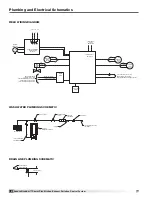
High Voltage Cable
High voltage cable is supplied to connect the ionizer/
collector sections of the precipitator to the ionizer and
collector terminals in the Power Pack. The red cable
(50 ft supplied) is used for the ionizer and the blue
cable (50 ft supplied) is used for the collector. Refer to
the ELECTRICAL section for details on wiring.


