background image

U-MATCH SERIES DC INVERTER AIR CONDITIONERS SERVICE MANUAL 

79 

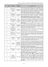
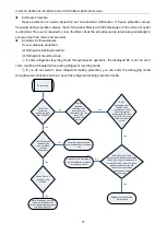
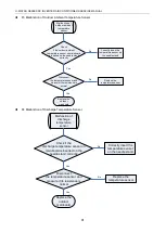
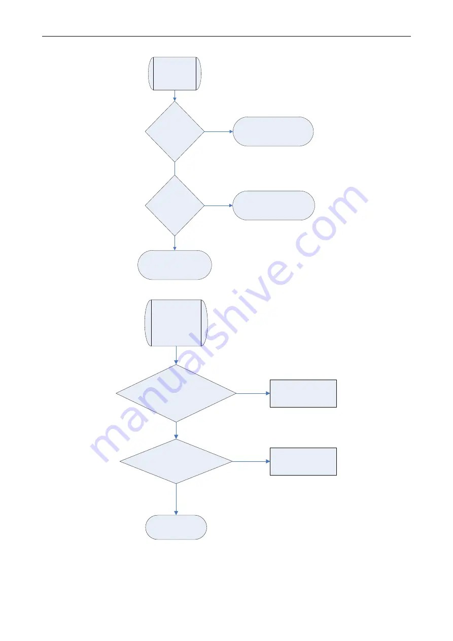
  E9 Full Water Protection 

E9 protection

If the unit is 

installed with 

water pump

No

Yes

Replace the water pump

Short circuit the full water 

protection interface on indoor 

mainboard according to the circuit 

diagram

Check if the 
water pump 

works normally

No

Replace the full water switch 

or make sure the float of full 

water switch works normally

Yes


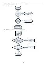
  F0 Malfunction of Indoor Ambient Temperature Sensor   

Malfunction of 

indoor ambient 

temperature 

sensor

Check if the 

indoor ambient temperature 

sensor on mainboard is inserted 

on the needle 

stand correctly

Disconnect 

the temperature sensor and 

measure if its resistance is 

normal

Correctly insert the 

temperature sensor 

on the needle stand

Replace the 

temperature sensor

Replace the indoor 

mainboard

Yes

No

No

Yes


Содержание U-MATCH B Series

Страница 1: ...T1 R410A 60Hz GC201604 І U MATCH SERIES DC INVERTERAIR CONDITIONERS SERVICE MANUAL U MATCH B SERIES WITH HIGH STATIC B SERIES SLIM DUCT DUCTED STYLE INDOOR UNITS ...

Страница 2: ...t and Centigrade 24 4 7 Enquiry of Ambient Temperature 24 4 8 Enquiry of Historical Malfunction 25 4 9 Debugging Function 25 5 INSTALLATION OF WIRED CONTROLLER 28 5 1 Standard Accessories 28 5 2 Installation Position and Requirement 29 5 3 Installation of Wired Controller 29 5 4 Removal of Wired Controller 30 6 TROUBLESHOOTING 31 7 CENTRALIZED CONTROLLER 32 7 1 Smart Zone Controller 32 7 2 Additio...

Страница 3: ... 2 2 Troubleshooting Flow Chart of Drive Malfunction 83 2 3 Interface 88 2 4 IPM PFC Testing Method 92 3 WIRING DIADRAM 94 3 1 Outdoor unit 94 3 2 Indoor unit 95 4 DISASSEMBLY AND ASSEMBLY PROCEDURE OF MAIN PARTS 96 4 1 Outdoor Unit 96 4 2 Indoor Unit 100 5 EXPLODED VIEWS AND SPARE PART LIST 104 5 1 Outdoor Unit 104 5 2 Indoor Unit 114 ...

Страница 4: ...U MATCH SERIES DC INVERTER AIR CONDITIONERS SERVICE MANUAL 1 PRODUCT ...

Страница 5: ...Model Name Product Code Power Supply V Ph Hz Appearance UMAT18HP230V1BO CF090W1040 208 230V 60Hz UMAT24HP230V1BO CF090W1060 208 230V 60Hz UMAT30HP230V1BO CF090W1050 208 230V 60Hz UMAT36HP230V1BO CF090W1030 208 230V 60Hz UMAT42HP230V1BO CF090W1020 208 230V 60Hz UMAT48HP230V1BO CF090W1070 208 230V 60Hz ...

Страница 6: ...24HP230V1BD CF022N0940 23800 27200 208 230V 60Hz UMAT30HP230V1BD CF022N1000 28300 31300 208 230V 60Hz UMAT36HP230V1BD CF022N0930 34100 40900 208 230V 60Hz UMAT42HP230V1BD CF022N0900 40900 47000 208 230V 60Hz UMAT48HP230V1BD CF022N0990 47700 54500 208 230V 60Hz Note 1 Ton 12000Btu h 3 517kW NOTES The universal outdoor units means that the customer can choose any of three kind of indoor unit to matc...

Страница 7: ... Only H Heat Pump without Aux Electric Heaters 4 Compressor Power Supply Type Code N Constant Frequency D DC Inverter A AC Inverter 5 Nominal Cooling Capacity Nominal Cooling Capacity Number 1000Btu h 6 Climate Type N Climate T1 Condition T Climate T3 Condition 7 Power Supply Code K 220 240V 50Hz M 380 415V 3N 50Hz D 208 230V 60Hz 8 Refrigerant 1 R22 2 R407C 3 R410A 9 Design Code Design Code A B C...

Страница 8: ...e T Floor ceiling Type 3 Product Type C Cool Only H Heat Pump without Aux Electric Heaters 4 Nominal Cooling Capacity Nominal Cooling Capacity Number 1000Btu h 5 Climate Type Omit Climate T1 Condition T Climate T3 Condition 6 Power Supply Code K 220 240V 50Hz M 380 415V 3N 50Hz D 208 230V 60Hz 7 Refrigerant 1 R22 2 R407C 3 R410A 8 Design Code Design Code A B C D Design Change Code 0 default 1 2 3 ...

Страница 9: ... 1000 585 1400 820 Rated Ext Static Pressure Pa InWg 50 0 2 50 0 2 Ext Static Pressure Range Pa InWg 0 100 0 0 4 0 200 0 0 8 Sound Pressure Level H M L dB A 40 39 36 28 47 46 44 40 Air Filter PP PP Drain Piping mm inch Φ30 1 5 Φ1 18 0 06 Φ20 1 2 Φ0 79 0 05 Outline Dimensions W H D mm inch 1280 270 560 50 4 10 6 22 0 1225 290 775 48 3 11 4 30 5 Net Weight kg lb 34 0 75 0 47 0 103 6 Outdoor Unit UMA...

Страница 10: ...Static Pressure Pa InWg 50 0 2 50 0 2 Ext Static Pressure Range Pa InWg 0 200 0 0 8 0 200 0 0 8 Sound Pressure Level H M L dB A 47 46 44 40 48 45 43 41 Air Filter PP PPKZ Drain Piping mm inch Φ20 1 2 Φ0 79 0 05 Φ20 1 2 Φ0 79 0 05 Outline Dimensions W H D mm inch 1225 290 775 48 3 11 4 30 5 1340 350 750mm 52 8 13 8 29 5 Net Weight kg lb 47 0 103 6 57 0 125 6 Outdoor Unit UMAT30HP230V1BO UMAT36HP230...

Страница 11: ...0 1175 Rated Ext Static Pressure Pa InWg 50 0 2 50 0 2 Ext Static Pressure Range Pa InWg 0 200 0 0 8 0 200 0 0 8 Sound Pressure Level H M L dB A 50 48 46 43 51 48 46 44 Air Filter PP PP Drain Piping mm inch Φ20 1 2 Φ0 79 0 05 Φ20 1 2 Φ0 79 0 05 Outline Dimensions W H D mm inch 340 350 750mm 52 8 13 8 29 5 340 350 750mm 52 8 13 8 29 5 Net Weight kg lb 59 0 130 0 59 0 130 0 Outdoor Unit Power Supply...

Страница 12: ...rical Data of Outdoor Unit Model Compressor Fan Motor Fuse Breaker Capacity Minimum Circuit Ampacity Power Supply Qty RLA FLA V Ph Hz A A A A UMAT18HP230V1BO 208V 230V 60Hz 1 11 2 0 9 5 25 15 5 UMAT24HP230V1BO 208V 230V 60Hz 1 17 2 0 9 5 35 23 UMAT30HP230V1BO 208V 230V 60Hz 1 20 1 0 9 5 45 26 5 UMAT36HP230V1BO 208V 230V 60Hz 1 22 8 1 2 5 70 30 5 UMAT42HP230V1BO 208V 230V 60Hz 1 23 0 0 9 5 70 31 UM...

Страница 13: ...mmunication lines between the wired controller and the indoor unit with their longest lengths of 30m 98 2 5feet Please select the appropriate line length as per the actual installation conditions The communication lines can not be twisted together It s recommended to use 8m 26 1 4feet long communication line The wire size of the communication line should be no less than 0 75mm2 AWG18 It s recommen...

Страница 14: ...U MATCH SERIES DC INVERTER AIR CONDITIONERS SERVICE MANUAL 11 CONTROL ...

Страница 15: ... 12 CONTROL 1 OPERATION FLOWCHART 1 1 Cooling Dry Operation Satisfying open Comp condition Temp of indoor Set temp Comp stop for 3 min N Y N Y Y N Open unit running at cool or dry mode Indoor fan run Comp and outdoor fan run Comp and outdoor fan stop Power On ...

Страница 16: ...ICE MANUAL 13 1 2 Heating Operation Satisfying open comp condition N Y N Y Y N Power On Comp and outdoor fan run Avoid cool wind only when comp start Temp of indoor Set temp Comp and outdoor fan stop Comp stop for 3 min Open unit running at heat mode ...

Страница 17: ...to Cool Dry Fan Heat mode can be selected circularly Auto mode is default after power on Under the Auto mode the setting temperature will not be displayed Under the Heat mode the initial value is 28 C 82 F Under other modes the initial value is 25 C 77 F AUTO COOL DRY FAN HEAT only for cooling and heating unit button Preset temperature can be decreased by pressing this button Pressing and holding ...

Страница 18: ...other press on the CLOCK button accepts the setting 12 00 is the default when the wireless remote controller is energized TIMER ON button When TIMER ON is activated ON will blink while the symbol will disappear Within 5 seconds it is allowed to set the ON time by pressing the button Each press will make the time increase or decrease one minute Besides the time can also be set by pressing the butto...

Страница 19: ...On and Sleep Off can be selected After powered on Sleep Off is defaulted Once the unit is turned off the Sleep function is canceled When Sleep is set to On the symbol of SLEEP will display Under the Fan and Auto modes this function is not available LIGHT button Press this button to select LIGHT on or off in the displayer When the LIGHT is set to on the icon will be displayed and the indicating lig...

Страница 20: ...4 Sleep function 5 Auto mode 6 COOL mode 7 DRY mode 8 FAN mode 9 HEAT mode 10 Health function 11 I Demand function 12 Vacation function 13 Status display of master and slave wired controller 14 Shield function The button operation temperature setting On Off operation Mode setting and Save setting are disabled 15 Fan speed 16 Memory function The unit will resume the original setting state after pow...

Страница 21: ...truction to Function of Buttons Table 2 3 2 Instruction to buttons of wired controller No Description Functions 1 Enter Cancel 1 Function selection and canceling 2 Press it for 5s to view the ambient temperature press Mode button to select viewing outdoor ambient temperature or indoor ambient temperature 2 1 Running temperature setting range of indoor unit 16 30 61 86 2 Timer setting range 0 5 24h...

Страница 22: ... the debugging menu Press Mode button to adjust the setting items and press or buttons to set the actual value 4 Mode and 6 Switch between Fahrenheit and Centigrade Under off state of the unit press Mode and buttons at the same time for 5s to switch between Fahrenheit and Centigrade 5 Function and 6 Viewing historical malfunction Continuously press Function and buttons for 5s to view historical ma...

Страница 23: ...monitor is to be set and the address setting range is 01 255 Enquiry and setting of wired controller s address is shown as Figure 2 3 4 below Figure 2 3 4 Enquiry and setting of wired controller s address 3 2 3 2 Setting of Master Slave Wired Controller s Address Under off status of the unit press Enter Cancel and Mode buttons at the same time for 5s to go to the enquiry and setting interface of m...

Страница 24: ...r clean reminder function The icon will blink and then enter setting of filter clean reminder function Timer zone displays the set pollution level and you can press or button to adjust the level Then press Enter Cancel button to turn on this function When filter clean reminder function is turned on press Function button to switch to filter clean reminder function The icon will blink and press or b...

Страница 25: ...ulated operating time of indoor unit There are 4 types of situations 1 Clean Reminder is off Timer zone shows 00 2 Slight pollution the former digit in timer zone shows 1 while the latter one shows 0 which indicates the accumulated operating time is 5500hr Each time the latter digit increases 1 the accumulated operating time increases 500hr When it reaches 9 it means the accumulated operating time...

Страница 26: ... clean reminder function is turned on the icon will be on 1 If cleaning time is not reached no mater the setting is changed or not the accumulated operating time won t be recalculated when pressing Enter Cancel button 2 If cleaning time is reached in unit on or off state will blink every 0 5s for reminder Press Function button to switch to icon and press and button to adjust the level Then press E...

Страница 27: ... the room card is inserted and stop working when the room card is not inserted when human sensitive function is selected the wired controller will work when it senses there is somebody in the room and stop working when it senses there is nobody in the room When the door control function senses the room card is not inserted or human sensitive function senses there is nobody in the room the wired co...

Страница 28: ...s the last malfunction 4 9 Debugging Function Under off state of the unit press Function and Timer buttons at the same time for 5s to go to the debugging menu Press Mode button to adjust the setting items and press or button to set the actual value 4 9 1 Setting ambient temperature sensor dual ambient temperature sensors function Under debugging state press Mode button to adjust to 00 in temperatu...

Страница 29: ...mode duct type unit and floor ceiling unit blow residual heat for 60s and then stop indoor unit while cassette type unit always operates in low fan speed and blows residual heat for 60s when there is malfunction Mode 2 After unit stops when reaching temperature point the indoor fan motor stops operation with a 10s delay no matter in cooling mode or in heating mode 4 9 6 Mode selecting of compresso...

Страница 30: ... fan mode of indoor fan motor Under debugging state press Mode button to adjust to 11 in temperature displaying zone Timer zone displays setting state and press or button to adjust There are 4 selections P0 LCD displays 00 P1 LCD displays 01 P3 LCD displays 02 P3 LCD displays 03 Note You can select P01 P02 P03 P04 P05 P06 P07 P08 P09 in fan mode of indoor fan motor which means different fan mode c...

Страница 31: ...3 15 Compensate 14 57 LCD displays 14 16 Compensate 15 59 LCD displays 15 Note Indoor ambient temperature compensation can be set through wired controller E g If 02 is selected it indicates the compensation temperature is 2 36 If the indoor ambient temperature detected by the temperature sensor at air return is 29 84 the ambient temperature after compensation is 29 84 2 36 27 48 After finishing se...

Страница 32: ...n interface of communication wire is correct otherwise it may lead to communication malfunction 2 The signal wires and communication wires of wired controller should be separated from power cord and connection wire between indoor unit and outdoor unit 3 If the air conditioner is installed at the strong electromagnetic interference place signal wire and communication wire of wired controller must u...

Страница 33: ... let this wire go through the hole at the back of wired controller s base plate 2 Fix the base plate and installation hole of the wall together with screw M4 25mm 3 16 1inch 3 Fix the above mentioned 2 core signal wire on the copper insert X1 and X2 with the equipped screws of wired controller 4 Fasten the wired controller s panel with its base plate together 5 4 Removal of Wired Controller Figure...

Страница 34: ...ion of outdoor main control memory chip PF Malfunction of electric box sensor H3 Compressor overload protection H4 Overload protection H5 IPM protection H6 Malfunction of DC fan motor H7 Drive desynchronizing protection HC pfc protection L1 Malfunction of humidity sensor Lc Start up failure Ld Compressor phase protection LF Power protection Lp Models of indoor unit and outdoor unit do not match wi...

Страница 35: ...rn off the unit and ask the professional for maintenance For example E1 means high pressure protection during operation Figure 2 6 1 7 CENTRALIZED CONTROLLER 7 1 Smart Zone Controller 7 1 1 Function The smart zone controller can directly control up to 16 sets of indoor units in a control network and is available to check the running status of any unit through the LCD including running mode timer f...

Страница 36: ...8 Wed 3 11 It is used for the switchover between unit 3 and unit 11 Under the timing or clock setting status it indicates Wednesday 9 Thu 4 12 It is used for the switchover between unit 4and unit 12 Under the timing or clock setting status it indicates Thursday 10 Fri 5 13 It is used for the switchover between unit 5and unit 13 Under the timing or clock setting status it indicates Friday 11 Sat 6 ...

Страница 37: ... unit 0 5 hour which will circulate every week 6 Set temperature Indoor unit code It displays the set temperature indoor unit code 01 16 and symbols of Celsius and Fahrenheit scale 7 Control mode It displays CENTER under the centralized control mode and no display under the single control mode 8 Ambient temperature Serial port It displays the ambient temperature serial port as well as symbols of C...

Страница 38: ...l accessories from Gree 1 Interface instructions 1 The interface printing is DOOR C and the type is B2B XH B The wires of door control accessories must be connected to this interface 2 Electrical characteristic none 3 Working principle when the card is inserted this interface is short circuited when the card is not inserted this interface is cut off Connect the door control detection port of indoo...

Страница 39: ...l control the ON OFF of unit according to the card state detected by door control detection board When the card is not connected the unit will turn to standby state If the unit is with wired controller icon will be displayed on the wired controller If the unit is without wired controller there will be no display The unit will control the ON OFF of unit according to the detected information 3 Setti...

Страница 40: ...pin GND current 150mA 3 Working principle when the module detects there is nobody in the room 2 pin and 3 pin are short circuited and they are low electrical level when there are somebody in the room 2 pin output is high electrical level 2 Function instructions In order to achieve this function set it through wired controller and refer to the following operation method It is defaulted that this fu...

Страница 41: ...Enter Cancel button to save and exit setting Now human sensitive function is activated The unit will memorize this setting status The setting value will be memorized after power failure The detailed setting is as shown in the Figure below Figure 2 7 8 Note When door control function and human sensitive function have been set at the same time it is defaulted that door control function is valid and ...

Страница 42: ...st set the address mode into long distance control address mode The address mode is defaulted to be connecting to centralized controller mode and the defaulted address is 1 3 Setting method 1 Firstly set the address mode of wired controller into centralized controller address mode The setting method is Under off state of the unit press Function and Timer buttons at the same time for 5s to go to th...

Страница 43: ...ting value range is 01 255 The setting method is Under off state of the unit press Function and Mode buttons at the same time for 5s to enter setting interface of wired controller address LCD displays address sequence Press or button to adjust the address sequence and then press Enter Cancel button to confirm The setting value will be memorized after power failure The detailed setting is as shown ...

Страница 44: ...ame network must be different otherwise the unit control will be affected Perform wiring when the unit power is cut off 7 2 4 Connect to interface of centralized controller The indoor unit is with the interface of centralized controller When centralized controller is connected centralized control of unit can be realized when the wired controller is not connected 1 Interface instruction 1 The print...

Страница 45: ...s 1 Under off state of the unit press Function and Timer buttons at the same time for 5s to go to the debugging menu Press Mode button to adjust to 10 in temperature displaying zone Timer zone displays setting state and press or button to adjust There are 2 selections Centralized controller address mode LCD displays 00 Long distance control address mode LCD displays 01 Choose the first selection a...

Страница 46: ...setting is as shown in the Figure below Figure 2 7 13 When the address is set the wired controller can be removed and connect the centralized controller to the indoor mainboard Then connect the required units to realize centralized control of these units Note When centralized controller is to be connected set the address mode into centralized controller address mode through wired controller Long d...

Страница 47: ...tion instructions under OFF state pressing Cool Heat button can turn on cooling heating mode Under unit ON state pressing Cool Heat button can turn off the unit When the unit is in cooling heating mode pressing any button can turn off the unit Figure 2 7 14 7 2 6 Malfunction output of relay There is malfunction outlet signal on the mainboard of indoor unit when the unit occurs unrecovered malfunct...

Страница 48: ...n the closed signal is detected when malfunction occurs this signal can be seen in monitoring system Figure 2 7 15 Malfunction output 3 Setting method Do not need to set this function Notes The interface voltage should be 220V AC intense current If malfunction light is connected please make sure its power is not too big it should be within 10W otherwise the relay on mainboard will be burnt ...

Страница 49: ...nterface 9 Interface of annunciator live wire 10 ON interface of fresh air valve 11 OFF interface of fresh air valve 12 Interface of annunciator neutral wire 13 Interface of DC motor 14 Mainboard grounding wire 15 Power live wire 16 Power neutral wire 17 Neutral wire of fresh air valve 18 Water pump interface 19 Live wire of fresh air valve 20 Interface of anion generator 21 Interface of auxiliary...

Страница 50: ...erator For the cold plasma anion generator connect the red line to HEALTH X4 and the blue line to N2 X6 according to the principle circuit The detector of cold plasma anion generator should be places at the air return The distance between two detectors should be 10mm 3 8inch L 25mm 1inch MOTOR WIRING DIAGRAM EARTH WIRING DIAGRAM M G G G POWER L1 L2 L1 L2 F C O 2BU 1RD 5WH 8BN COOL PLASMA GENERATOR...

Страница 51: ...ITIONERS SERVICE MANUAL 48 7 2 9 Chassis electric heating belt of outdoor unit is optional When outdoor ambient temperature is very low electric heating belt can be equipped on the chassis to prevent freezing of the chassis Figure 2 7 18 ...

Страница 52: ...U MATCH SERIES DC INVERTER AIR CONDITIONERS SERVICE MANUAL 49 INSTALLATION ...

Страница 53: ...tored thus to avoid possible explosion or fire due to leakage 1 1 2 Installation Site Ensure the top hanging piece has strong strength to withstand the weight of the unit The drainage pipe has convenient flow of water There is no obstacle blocking the return air inlet and exhaust outlet so as to ensure sound air circulation The installation spaces required by the drawing must be ensured so as to p...

Страница 54: ...ing lines of wire controller indoor unit and outdoor unit must be ready before the installation so as to achieve smooth installation Drill an opening on the ceiling Maybe it is required to support the ceiling to ensure the evenness of it and avoid the vibration of it Consult with the user or a construction company for details In case the strength of ceiling is not enough use angle iron sections to...

Страница 55: ...side of the unit is in the negative pressure status it is required to set up a backwater elbow The requirements is A B 0 145P 10000 20 25 4 inch P is the absolute pressure inside the unit The unit of the pressure is psig Figure 3 1 5 1 1 4 Dimension Data For the units 18 30k E Max A C D B F Max G I H J Gas Pipe Liquid Pipe Air Intake Drainage Pipe Electric Box Figure 3 1 6 ...

Страница 56: ...3 3 8 515 20 3 8 820 32 1 4 1160 45 5 8 1280 50 3 8 560 22 1000 39 1 2 160 6 1 4 235 9 1 4 270 10 1 2 UMAT24HP230V1BD 1010 39 3 4 750 29 1 2 820 32 1 4 1115 43 7 8 1225 48 1 4 775 30 1 2 980 38 5 8 160 6 1 4 230 9 290 11 3 8 UMAT30HP230V1BD UMAT36HP230V1BD 1175 46 1 4 645 25 3 8 850 33 1 2 1150 45 1 4 1340 85 1 4 750 29 1 2 980 38 5 8 19 5 7 5 8 230 9 350 13 3 4 UMAT42HP230V1BD UMAT48HP230V1BD ...

Страница 57: ...e for fixing the hanger hook 4 4 sets used for ceiling mounting of the indoor unit Nut and spring gasket 4 Hook 4 Used for ceiling mounting of the indoor unit Strap 4 or 8 pcs 4 pcs for 18kBtu h unit and 8 pcs for others Wired controller 1 Remote controller 1 Battery 2 Fexible pipe 0 2 or 4 pcs 0 pc for 18 kBtu h unit 2 pcs for 22 5 27kBtu h unit and 4 pcs for 36 45kBtu h unit Power cord 1 2 pcs 2...

Страница 58: ... leaks 1 Install the drain hose with downward gradient 1 50 to 1 100 and no risers or traps are used for the hose Figure 3 1 8 2 Be sure there is no crack or leak on the drain hose to avoid the formation of air pocket Figure 3 1 8 3 When the hose is long install supporters Figure 3 1 9 4 Always use the drain hose which has been insulated properly Drain hose Arrange the drain hose lower than this d...

Страница 59: ...ry the drain port is defaulted to be the one on the left side electric box side the port on right side has been plugged 8 When using the drain port on the right side of the unit reinstall the drain cap to the left side drain port Figure 3 1 12 Figure 3 1 12 CAUTION Always check that the drain cap is installed to the unused drain port and is fastened with the nylon fastener If the drain cap is not ...

Страница 60: ...ttom are defaulted to be factory plugged with drain caps After the installation of the drain hose these two drain ports also need to be insulated properly with the same way aforementioned 4 The drain hose for the unit with the condensate pump should be arranged as shown in the figure below Ceiling Hoisting stand Clamp attachment Drain hose attachment Drain raising hose 300mm 11 3 4inch 1000 1500mm...

Страница 61: ...ch Figure 3 1 18 Supply Air Outlet C D Figure 3 1 19 Return Air Inlet Table 3 1 3 Unit mm inch Item Model Supply Air Outlet Return Air Inlet A B C D UMAT18HP230V1BD 158 6 1 4 818 32 1 4 994 39 1 8 195 7 5 8 UMAT24HP230V1BD 160 6 1 4 820 32 1 4 980 37 5 8 230 9 UMAT30HP230V1BD 160 6 1 4 820 32 1 4 980 37 5 8 230 9 UMAT36HP230V1BD 195 7 5 8 852 33 1 2 980 37 5 8 230 9 UMAT42HP230V1BD 195 7 5 8 852 3...

Страница 62: ... 21 3 If the bottom return air is desired just change the place of the rectangular flange and the return air cover plate 4 Connect one end of the return air duct to the return air outlet of the unit by rivets and the other to the return air louver For the sake of the convenience to freely adjust the height a cutting of canvas duct will be helpful which can be reinforced and folded by 8 iron wire 5...

Страница 63: ...o move the unit with the packaging box Even though it is not permitted to do like this under special occasions do not remove the packaging box thus to avoid loosening or falling during handling Confirm if the installing foundation is solid When this unit is to be installed on the metal section of the building make sure that the electrical insulation must comply with applicable standards Ensure tha...

Страница 64: ...ation so that the machine can breathe and exhaust enough air Ensure that there is no obstruction at the inlet and outlet of the machine If any please remove the obstructions blocking the air inlet and outlet If the outdoor unit is installed on concrete or solid ground it shall be fixed by using M10 bolts and nuts And ensure that the machine is kept vertical and horizontal The outdoor unit must be ...

Страница 65: ...50 53 1 8 570 22 1 2 375 14 3 4 UMAT48HP230V1BO 3 REFRIGERATION PIPING WORK 3 1 Refrigeration Piping Work Procedures and Caution in Connecting 3 1 1 Flare Processing 1 Cut the connection pipe with the pipe cutter and remove the burrs 2 Hold the pipe downward to prevent cuttings from entering the pipe 3 Remove the flare nuts at the stop valve of the outdoor unit and inside the accessory bag of the ...

Страница 66: ...Bend the pipe with a radius of curvature of 150 mm 5 7 8inch or over If the pipe is bent repeatedly at the same place it will break 3 1 3 Connecting the Pipe at the Indoor Unit Side Detach the caps and plugs from the pipes CAUTION Be sure to apply the pipe against the port on the indoor unit correctly If the centering is improper the flare nut cannot be tightened smoothly If the flare nut is force...

Страница 67: ...5 40N m 26 29ft 1b 12 7mm 1 2 inch 45 50N m 33 37ft 1b 16mm 5 8 inch 60 65N m 44 48ft 1b CAUTION Be sure to connect the gas pipe after connecting the liquid pipe completely 3 1 4 Connecting the Pipe at the Outdoor Side Unit Tighten the flare nut of the connection pipe at the outdoor unit valve connector The tightening method is the same as that as at the indoor side Figure 3 2 2 3 1 5 Checking the...

Страница 68: ...of the manifold valve assembly should be kept closed otherwise evacuation would fail The evacuation duration depends on the unit s capacity generally 20 minutes for the 18k units 30 minutes for the 24 30 36k units 45 minutes for the 42 48k units And verify if the pressure gauge at the low pressure side of the manifold valve assembly reads 1 0MPa 145psig if not it indicates there is leak somewhere ...

Страница 69: ...ge Refrigerant suitable for a piping length of 7 6m 25feet is charged in the outdoor unit at the factory When the piping is longer than 7 6m 25feet additional charging is necessary For the additional amount see Table 3 2 3 Table 3 2 3 Item Model Additional Refrigerant Amount for Extra Pipe 18k 33g per 1 5m 1 2 ounce per 5 feet 24k 48k 81g per 1 5m 2 9 ounce per 5 feet When the height difference be...

Страница 70: ...n verify that the voltage is within the 187 252V range for single phrase unit Always use a special branch circuit and install a special receptacle to supply power to the air conditioner Use a special branch circuit breaker and receptacle matched to the capacity of the air conditioner The special branch circuit breaker is installed in the permanent wiring Always use a circuit that can trip all the ...

Страница 71: ...e terminal screw using a screwdriver 2 For strand wiring Figure 3 2 6 1 Cut the wire end with a wire cutter or wire cutting pliers then strip the insulation about 10mm 3 8inch 2 Using a screwdriver remove the terminal screw s on the terminal board 3 Using a round terminal fastener or pliers securely clamp a round terminal to each stripped wire end 4 Position the round terminal wire and replace and...

Страница 72: ...e terminal block Imperfect installation may cause a fire Always fasten the outside covering of the connection cord with cord clamps If the insulator is not clamped electric leakage may occur Always connect the ground wire 4 Electric wiring between the indoor and outdoor units Single phase units 36 42k Figure 3 2 9 5 Electric wiring of indoor unit side Remove the electric box cover from the electri...

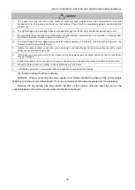
Страница 73: ...er Tighten the indoor outdoor connection cord and power cord respectively on the terminal boards with screws Faulty connection may cause a fire If the indoor unit connection cord to the outdoor unit and power supply are wired incorrectly the air conditioner may be damaged Connect the indoor unit connection cord properly based on the corresponding marks as shown in Figure 3 2 9 Ground both the indo...

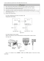
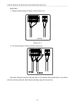
Страница 74: ...pply for indoor unit and outdoor unit 24k 60k 1 2 Figure 3 2 13 2 The Power supply for indoor units from outdoor unit 1 2 Power lines should go along the right side plate Communication lines between indoor and outdoor units also should go along the right side plate and keep away from power lines ...

Страница 75: ...U MATCH SERIES DC INVERTER AIR CONDITIONERS SERVICE MANUAL 72 MAINTENANCE ...

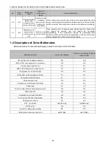
Страница 76: ...exiting refrigerant recycling mode the code will disappear 4 E4 Compressor high discharge temperature protection Compressor discharge temperature is high If outdoor unit detects that the discharge temperature is higher than protective temp value the unit will report high discharge temperature protection If the protection occurs over 6 times the unit cannot be recovered automatically Switch off the...

Страница 77: ... ee Malfunction of outdoor drive memory chip Outdoor drive board If the memory chip of outdoor drive board is broken the unit cannot be started The unit cannot be recovered automatically If the malfunction cannot be eliminated after switching off the unit and then energizing the unit for several times please replace the outdoor drive board 20 H3 Compressor overload protection Compressor overload s...

Страница 78: ...n energizing the unit for several times please replace the outdoor main control board 1 2 Description of Drive Malfunction Main board dual 8 numeral tube Display Codes for Outdoor Unit of 09 48k Malfunction Item Indoor Unit Display Outdoor unit display of dual 8 numeral tube DC busbar over voltage protection PH PH IPM or PFC over temperature protection P8 P8 Current sense circuit error Pc Pc IPM o...

Страница 79: ...e liquid valve and gas valve of outdoor unit Check if the liquid valve and gas valve of outdoor unit open completely No Yes Yes Check if the air outlet of outdoor fan motor or indoor fan motor is normal Clear the obstacle at indoor and outdoor air outlet or air return port to ensure smooth air outlet No Reconnect wire according to the circuit diagram No Replace the high pressure switch Yes Replace...

Страница 80: ... and then cancel the refrigerant lacking protection mode E3 protection Check if the system low pressure is lower than 0 05MPa No Yes Charge refrigerant according to the requirement and then turn on the unit to see if E3 protection still occurs Yes Enter debugging mode through wired controller and select without refrigerant lacking protection then turn on the unit to see if E3 protection still occu...

Страница 81: ... after vacuum pumping and pressure retaining are passed Yes Replace the outdoor main control board No Replace the discharge temperature sensor E6 Communication Malfunction Communication malfunction Check if the communication wire between indoor unit and outdoor unit is connected well Check if there is open circuit in the communication wire between indoor unit and outdoor unit Reconnect the communi...

Страница 82: ...ally No Replace the full water switch or make sure the float of full water switch works normally Yes F0 Malfunction of Indoor Ambient Temperature Sensor Malfunction of indoor ambient temperature sensor Check if the indoor ambient temperature sensor on mainboard is inserted on the needle stand correctly Disconnect the temperature sensor and measure if its resistance is normal Correctly insert the t...

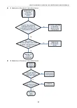
Страница 83: ...orrectly insert the temperature sensor on the needle stand Replace the temperature sensor Replace the indoor mainboard Yes No No Yes F2 Malfunction of Condenser Temperature Sensor Malfunction of condenser temperature sensor Check if the condenser temperature sensor on mainboard is inserted on the needle stand correctly Disconnect the temperature sensor and measure if its resistance is normal Corre...

Страница 84: ...ormal Correctly insert the temperature sensor on the needle stand Replace the temperature sensor Replace the outdoor mainboard Yes No No Yes F4 Malfunction of Discharge Temperature Sensor Malfunction of discharge temperature sensor Check if the discharge temperature sensor on mainboard is inserted on the needle stand correctly Disconnect the temperature sensor and measure if its resistance is norm...

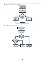
Страница 85: ...Outdoor Fan Motor Malfunction of discharge temperature sensor Check if the control wire of outdoor fan motor is connected on the outdoor mainboard correctly Replace the outdoor fan motor and then restart the unit to see if there still is malfunction of outdoor fan motor Correctly connect the control wire of fan motor on the mainboard Operate the unit with the new motor Replace the outdoor mainboar...

Страница 86: ...ct the control wire of fan motor on the mainboard Operate the unit with the new motor Replace the indoor mainboard Yes No No Yes 2 2 Troubleshooting Flow Chart of Drive Malfunction Note For Outdoor Unit Drive Inverter by Single phase Motor P0 Drive module reset P7 IPM or PFC temperature sensor error PA AC current protection input side PC Current sense circuit error Hc PFC protection 48k only P0 P7...

Страница 87: ...No Work normally Replace the mainboard Yes Tighten the IPM or PFC module PH DC busbar over voltage protection PL DC busbar under voltage protection PH or PL is displayed on the wired controller PH or PL is displayed in the mainboard 88 indicating lamp Is input voltage ranged from 185VAC to 264VAC Yes Replace the mainboard Does it work normally No Replace the compressor Work normally Yes Please cut...

Страница 88: ... Work normally Yes No P5 Compressor current protection H7 Compressor motor desynchronizing H5 IPM protection Ld Phase loss P5 H7 H5 or Ld is displayed in the mainboard 88 indicating lamp Is the compressor phase sequence right Yes Replace the mainboard Does it work normally No Replace the compressor Work normally Yes adjust the compressor phase sequence Is the compressor wire terminals tightened Ti...

Страница 89: ...layed in the mainboard 88 indicating lamp Is the PFC wire tightened or is the sequence right Tighten the PFC wire or adjust the sequence Replace the mainboard Yes No Work normally ee driving board chip error 18 36k Yes Yes ee is displayed on the wired controller Is the jumper loose Work Normally Tighten the jumper Replace the mainboard No ...

Страница 90: ... mainboard 88 indicating lamp Is the motor phase sequence right Yes Replace the mainboard Does it work normally No Replace the outdoor fan Work normally Yes Adjust the motor phase sequence Is the Fan wire terminal loose Tighten the fan wiring terminal Yes No No H6 is displayed on the wired controller ...

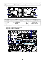
Страница 91: ... DC fan motor 1 pin DC bus voltage 2 pin Suspended 3 pin DC bus GND 4 pin 15V 5 pin Control signal input 6 pin Not connected 5 DC_MOTOR1 DC fan motor1 1 pin Power supply of fan motor 3 pin Fan GND 4 pin 15V 5 pin Signal control 6 pin Signal Feedback Interface of DC fan motor 1 pin DC bus voltage 2 pin Suspended 3 pin DC bus GND 4 pin 15V 5 pin Control signal input 65 pin DC fan motor feedback 6 CN...

Страница 92: ...mperature sensor 5 6 pin Discharge temperature sensor 15 FA Electronic expansion valve line 1 to 4 pin Drive impulse output 5 pin 12V Interface of electronic expansion valve 1 to 4 pin Drive impulse output 5 pin 12V 16 HEAT Compressor electrical heater Compressor electric heating belt 17 VA 1 Chassis electrical heater Chassis electric heating belt 18 4V 4 way valve 4 way valve UMAT18HP230V1BO UMAT...

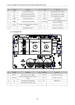
Страница 93: ...Interface No Printing Interface 1 N OUT1 Neutral wire output 1 white only for 18K 2 N OUT Neutral wire output white 3 L OUT Live wire output red 4 E1 Grounding wire 5 E2 Reserved 6 AC L Live wire input red 7 AC N Neutral wire input white UMAT36HP230V1BO UMAT42HP230V1BO UMAT48HP230V1BO 1 Drive Board 11 1 8 2 3 4 5 6 7 9 10 12 13 14 ...

Страница 94: ...AG1 Reserved 9 COMM Communication interface 10 DC BUS1 DC bus electric discharging needle stand for testing 11 DC BUS DC bus interface connect to filtering board 12 U Compressor Phase U 13 V Compressor Phase V 14 W Compressor Phase W 2 Filtering Board 3 4 5 6 7 1 2 No Printing Interface No Printing Interface 1 N OUT Neutral wire output white 2 L OUT Live wire output red 3 DC BUS DC bus interface c...

Страница 95: ...en it indicates the IPM module is normal If any measured valve is 0 it indicates the IPM is damaged 2 4 2 Method of Testing PFC Module Short Circuit only for GUHD48ND3FO 1 Preparation before test prepare a universal meter and turn to its diode option and then remove the wires L1 2 L2 1 after it is powered off for one minute 2 Testing Steps Step 1 put the black probe on the place P and the red one ...

Страница 96: ...U MATCH SERIES DC INVERTER AIR CONDITIONERS SERVICE MANUAL 93 ...

Страница 97: ...INVERTER AIR CONDITIONERS SERVICE MANUAL 94 UMAT36HP230V1BO UMAT42HP230V1BO UMAT48HP230V1BO 3 WIRING DIADRAM 3 1 Outdoor unit The actual wiring should always refer to the wiring diagram of the unit Model UMAT36HP230V1BO ...

Страница 98: ...E MANUAL 95 Model UMAT42HP230V1BO M1 M2 3 2 Indoor unit The actual wiring should always refer to the wiring diagram of the unit 3 2 1 Duct Type Model UMAT18HP230V1BD UMAT24HP230V1BD UMAT30HP230V1BD Model UMAT36HP230V1BD UMAT42HP230V1BD UMAT48HP230V1BD ...

Страница 99: ...ernal casing 1 Remove the top cover and handle 2 Remove the grille outer case and right side plate 2 Remove motor 1 Remove the blade nut and then remove the blade 2 Remove the motor from motor support 3 Remove compressor 1 Discharge the refrigerant inside the pipeline and recycle the refrigerant during discharging 2 Unsolder the 4 way valve assy from compressor 3 Remove the nut fixing compressor 4...

Страница 100: ...l casing 1 Remove the top cover and handle 2 Remove the grille outer case front side plate and right side plate 2 Remove motor 1 Remove the blade nut and then remove the blade 2 Remove the motor from motor support 3 Remove compressor 1 Discharge the refrigerant inside the pipeline and recycle the refrigerant during discharging 2 Unsolder the 4 way valve assy from compressor 3 Remove the nut fixing...

Страница 101: ...n 1 Remove external casing 1 Remove the top cover and handle 2 Remove the grille outer case and right side plate 2 Remove motor 1 Remove the blade nut and then remove the blade 2 Remove the motor from motor support 3 Remove gas liquid separator 1 Discharge the refrigerant inside the pipeline and recycle the refrigerant during discharging 2 Unsolder the 4 way valve assy from gas liquid separator 3 ...

Страница 102: ... fixing compressor 4 Take away the compressor from chassis 5 Assemble unit Assemble the unit in the reverse procedures of disassembly 42 48k Disassembly and Assembly of external casing Remark Step Illustration Handling Instruction 1 Remove external casing 1 Remove the top cover and handle 2 Remove the grille outer case and right side plate 2 Remove motor 1 Remove the blade nut and then remove the ...

Страница 103: ...emove compressor 1 Discharge the refrigerant inside the pipeline and recycle the refrigerant during discharging 2 Unsolder the 4 way valve assy from compressor 3 Remove the nut fixing compressor 4 Take away the compressor from chassis 5 Assemble unit Assemble the unit in the reverse procedures of disassembly 4 2 Indoor Unit 4 2 1 Duct type Removal and Assembly of Fan Motor Remarks Before removing ...

Страница 104: ...d motor Use inner hexagonal spanner to loosen the screws on fan and remove the clamp fixing the motor 6 Replace the motor Firstly disengage the motor from motor support Then sequentially disengage the fan sub assembly form the motor shaft Remove the motor from the air inlet and replace with new motor In which for the motor with automatic motor support the motor support shall be removed in advance ...

Страница 105: ...ion of the arrow 3 Disassembly of electric parts box Disassemble the fastening screw and remove the electrical parts box As is shown in the graph there are 2 fastening screws in the circle and the screws in the direction of arrow shall be disassembled too Disassembly of water containing plate Remark Make sure that the power supply is cut off before disassembling and protect all the parts during di...

Страница 106: ... fin If the time for disassembly shall be long put the copper tube under pressurized condition Step Illustration Handling Instruction 1 Disassembly of fixing screws on the side panels of evaporator Disassemble the fastening screw connecting left and right side panels on the evaporator and the upper cover plate As is shown in the arrows direction in Graph 2 Disassemble fastening screws connecting e...

Страница 107: ...U MATCH SERIES DC INVERTER AIR CONDITIONERS SERVICE MANUAL 104 5 EXPLODED VIEWS AND SPARE PART LIST 5 1 Outdoor Unit Model UMAT18HP230V1BO Exploded Views and spare parts list ...

Страница 108: ...6 Valve Support Assy 01715010P 1 17 Right Side Plate 0130509403P 1 18 Silencer 07245007 1 19 Handle Assy 02113109 1 20 Strainer 07212403 1 21 Strainer 07220019 1 22 Strainer 0721004501 1 24 Electric Expand Valve Fitting 4300876704 1 23 Electronic Expansion Valve 07134601 1 25 4 Way Valve 430004032 1 26 Magnet Coil 4300040045 1 27 Inductance 4312002001 1 28 Rear Grill 01473043 1 29 Clapboard Sub As...

Страница 109: ...U MATCH SERIES DC INVERTER AIR CONDITIONERS SERVICE MANUAL 106 Model UMAT24HP230V1BO Exploded Views and spare parts list ...

Страница 110: ...e Protect Switch 4602000902 1 18 Right Side Plate Sub Assy 01315200069P 1 19 Handle Assy 02113109 1 20 Temperature Sensor 3900028020G 1 21 Rear Grill 01475013 1 22 Clapboard Sub Assy 01245200010 1 23 Strainer 07225088 1 24 PFC Inductance 43128003 1 25 Bidirection Strainer 07220016 1 26 Condenser Assy 01125200184 1 27 Electronic Expansion Valve 07334447 1 28 Electric Expand Valve Fitting 4304413208...

Страница 111: ...U MATCH SERIES DC INVERTER AIR CONDITIONERS SERVICE MANUAL 108 Model UMAT30HP230V1BO Exploded Views and spare parts list ...

Страница 112: ...157 1 14 Silencer 07245012 1 15 Pressure Protect Switch 4602000902 1 16 Pressure Protect Switch 46020003 1 17 Valve Support Sub Assy 0171501201P 1 18 Right Side Plate Sub Assy 01315200069P 1 19 Cut off Valve 071302391 1 20 Handle Assy 02113109 1 21 Temperature Sensor 3900028020G 1 22 Rear Grill 01475013 1 23 Clapboard Sub Assy 01245200006 1 24 Strainer 07225088 1 25 Bidirection Strainer 07220016 1...

Страница 113: ...00007 1 39 Radiator 49018000042 1 40 PFC Inductance 43128003 1 41 Inductance Box Sub assy 01395200176 1 42 Electric Box Assy 01395200488 1 43 Motor Support Assy 01805200160 1 44 Fan Motor 15702802 1 45 Left Side Plate 01305043P 1 Model UMAT36HP230V1BO Exploded Views and spare parts list ...

Страница 114: ...045 1 18 Electronic Expansion Valve 07334194 1 19 Pressure Protect Switch 46020003 1 20 Pressure Protect Switch 4602000902 1 21 Valve Support Sub Assy 01805200222P 1 22 Silencer 07245012 1 23 Strainer 07215201 1 24 Right Side Plate Sub Assy 0131520006801P 1 25 Temperature Sensor 39008000049G 1 26 Rear Grill 01475012 1 27 Clapboard Sub Assy 0124525303 1 28 Condenser Assy 01125200196 1 29 Baffle Pla...

Страница 115: ...U MATCH SERIES DC INVERTER AIR CONDITIONERS SERVICE MANUAL 112 Model UMAT42HP230V1BO UMAT48HP230V1BO Exploded Views and spare parts list ...

Страница 116: ...e 07133844 1 19 Pressure Protect Switch 46020003 1 20 Valve Support Sub Assy 01805200204P 1 21 Cut off Valve 07130209 1 22 Rear Side Plate Sub Assy 01315200088P 1 23 Temperature Sensor 3900028025G 1 24 Rear Grill 01574100004 1 25 Clapboard 0124520000701 1 26 Bidirection Strainer 07220016 1 27 Strainer 07415210 1 28 Electronic Expansion Valve 07135176 1 29 Electric Expand Valve Fitting 43000344 1 3...

Страница 117: ...U MATCH SERIES DC INVERTER AIR CONDITIONERS SERVICE MANUAL 114 5 2 Indoor Unit Duct Type Model GFH18D3F2I exploded view and spare parts list ...

Страница 118: ...over Plate Sub Assy 01265304 1 9 Water Tray Assy 01285317 1 10 Left Side Plate Assy 01314155 1 11 Choke Plug of Drain Pipe 76712455 1 12 Evaporator Assy 01025200050 1 13 Filter Sub Assy 11125303 2 14 filter guide groove sub assy 02285301 1 15 Hook 02112446 4 16 Top Cover Board Assy 01265226 1 17 Tube sensor 3900012128 1 18 Ambient Temperature Sensor 3900012123 1 19 Display Board 30294000007 1 20 M...

Страница 119: ...U MATCH SERIES DC INVERTER AIR CONDITIONERS SERVICE MANUAL 116 Model UMAT18HP230V1BD with water pump exploded view and spare parts list ...

Страница 120: ... Terminal Board 4201025301 1 11 Main Board 30224000030 1 12 Electric Box Assy 01395200453 1 13 Right Side Plate Sub Assy 01315200057 1 14 Water Pump Assy 15405392 1 15 Centrifugal fan assy 15405200029 1 16 Blower 15012458 1 17 Brushless DC Motor 15705200006 1 18 Supporter 01804100140 1 19 Support Sub assy 01805200164 1 20 Blower Mounting Plate Sub Assy 01325200039 1 21 Blower 15012454 1 22 Hook 02...

Страница 121: ...U MATCH SERIES DC INVERTER AIR CONDITIONERS SERVICE MANUAL 118 Model GFH24D3F2I GFH30D3F2I exploded view and spare parts list ...

Страница 122: ...d 30226000065 2 11 Terminal Board 42010194 1 12 Terminal Board 4201025301 1 13 Main Board 30224000065 1 14 Temperature Sensor 390001921G 1 15 Ambient Temperature Sensor 3900012123 1 16 Display Board 30294000007 1 17 Blower Mounting Plate Sub Assy 01325200044 1 18 Propeller Housing Upper 26904100051 2 19 Brushless DC Motor 1570940000601 1 20 Centrifugal Fan 10424100001 2 21 Hook 02112466 4 22 Top C...

Страница 123: ...U MATCH SERIES DC INVERTER AIR CONDITIONERS SERVICE MANUAL 120 Model UMAT24HP230V1BD UMAT30HP230V1BD exploded view and spare parts list ...

Страница 124: ...470 1 12 Terminal Board 42011149 1 13 Filter Board 30226000065 2 14 Terminal Board 42010194 1 15 Terminal Board 4201025301 1 16 Main Board 30224000065 1 17 Temperature Sensor 390001921G 1 18 Ambient Temperature Sensor 3900012123 1 19 Display Board 30294000007 1 20 Blower Mounting Plate Sub Assy 01325200044 1 21 Propeller Housing Upper 26904100051 2 22 Brushless DC Motor 1570940000601 1 23 Centrifu...

Страница 125: ...U MATCH SERIES DC INVERTER AIR CONDITIONERS SERVICE MANUAL 122 Model GFH36D3F2I exploded view and spare parts list ...

Страница 126: ...8 1 11 Propeller Housing Lower 26905200011 2 12 Top Cover Board Assy 01265200045 1 13 Water Tray Assy 01285200025 1 14 Choke Plug of Drain Pipe 76712455 2 15 Right Side Plate Assy 01315200161 1 16 Electric Box Assy 01395200458 1 17 Water Pump 4313822001 1 18 Water Level Switch 4501270301 1 19 Pump Drainpipe 05235301 1 20 Evaporator Assy 01025200133 1 21 Filter Sub Assy 111253036 2 22 Terminal Boar...

Страница 127: ...U MATCH SERIES DC INVERTER AIR CONDITIONERS SERVICE MANUAL 124 Model UMAT36HP230V1BD exploded view and spare parts list ...

Страница 128: ...0008 1 11 Propeller Housing Lower 26905200011 2 12 Top Cover Board Assy 01265200045 1 13 Water Tray Assy 01285200025 1 14 Choke Plug of Drain Pipe 76712455 2 15 Right Side Plate Assy 01315200161 1 16 Electric Box Assy 01395200458 1 17 Water Pump 4313822001 1 18 Water Level Switch 4501270301 1 19 Pump Drainpipe 05235301 1 20 Evaporator Assy 01025200133 1 21 Filter Sub Assy 111253036 2 22 Terminal B...

Страница 129: ...U MATCH SERIES DC INVERTER AIR CONDITIONERS SERVICE MANUAL 126 Model GFH42D3F2I GFH48D3F2I exploded view and spare parts list ...
Страница 130: ... Sub Assy 01315200091 1 10 Blower Mounting Plate Sub Assy 01325200057 1 11 Propeller Housing Lower 26905200011 2 12 Top Cover Board Assy 01265200045 1 13 Choke Plug of Drain Pipe 76712455 1 14 Electric Box Assy 01395200454 1 15 Right Side Plate Assy 0131520006601 1 16 Water Tray Assy 01285200025 1 17 Evaporator Assy 01025200055 1 18 Filter Sub Assy 111253036 2 19 Terminal Board 42010194 1 20 Termi...

Страница 131: ...U MATCH SERIES DC INVERTER AIR CONDITIONERS SERVICE MANUAL 128 Model UMAT42HP230V1BD UMAT48HP230V1BD exploded view and spare parts list ...
Страница 132: ...Water Tray Assy 01285200025 1 13 Filter Sub Assy 111253036 2 14 Evaporator Assy 01025200054 1 15 Choke Plug of Drain Pipe 76712455 2 16 Left Side Plate Sub Assy 01315200064 1 17 Ambient Temperature Sensor 3900012123 1 18 Tube sensor 3900012128 1 19 Display Board 30294000007 1 20 Bottom Cover Plate Assy 01265200081 1 21 Hook 02205209 4 22 Front Side Plate Sub Assy 01315200091 1 23 Brushless DC Moto...

Страница 133: ...JF00302978 www greecomfort com info greecomfort com Cat no GREE_UMAT_B_SERVICE_010119 Contractor Support Number for Gree Branded Equipment Sold in the U S 888 850 7928 ...

Отзывы: