GREAT PLANES Super Skybolt Скачать руководство пользователя страница 26

At this stage the model should be in ready-to-fly condition
with all of the systems in place including the engine, landing
gear, covering and paint, and the radio system.

❏ 

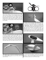
1. Use a felt-tip pen or 1/8" [3 mm]-wide tape to accurately

mark the C.G. on the bottom of the top wing on both sides
of the fuselage. The C.G. is located 4-5/8" [118 mm] back
from the leading edge of the top wing.

❏ 

2. With the wing attached to the fuselage, all parts of the

model installed (ready to fly) and an empty fuel tank, lift the
model at the balance point you marked.

❏ 

3. If the tail drops, the model is “tail heavy” and the battery

pack and/or receiver must be shifted forward or weight must
be added to the nose to balance. If the nose drops, the
model is “nose heavy” and the battery pack and/or receiver
must be shifted aft or weight must be added to the tail to
balance. If possible, relocate the battery pack and receiver
to minimize or eliminate any additional ballast required. If
additional weight is required, nose weight may be easily

added by using a “spinner weight” (GPMQ4645 for the 1 oz.
[28 g] weight, or GPMQ4646 for the 2 oz. [57 g] weight). If
spinner weight is not practical or is not enough, use Great
Planes (GPMQ4485) “stick-on” lead. A good place to add
stick-on nose weight is to the firewall (don’t attach weight to
the cowl–it is not intended to support weight). Begin by
placing incrementally increasing amounts of weight on the
fuse over the firewall until the model balances. Once you
have determined the amount of weight required, it can be
permanently attached. If required, tail weight may be added
by cutting open the bottom of the fuse and gluing it
permanently inside.

Note: Do not rely upon the adhesive on the back of the lead
weight to permanently hold it in place. Over time, fuel and
exhaust residue may soften the adhesive and cause the
weight to fall off. Use #2 sheet metal screws, RTV silicone or
epoxy to permanently hold the weight in place.

❏ 

4. IMPORTANT! If you found it necessary to add any

weight, recheck the C.G. after the weight has been installed.

❏ 

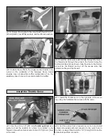
1. With the wing level, have an assistant help you lift the

model by the engine propeller shaft and the bottom of the
fuse under the TE of the fin. Do this several times.

❏ 

2. If one wing always drops when you lift the model, it means

that side is heavy. Balance the airplane by adding weight to the
other wing tip. An airplane that has been laterally balanced
will track better in loops and other maneuvers.

No matter if you fly at an AMA sanctioned R/C club site or if you
fly somewhere on your own, you should always have your name,
address, telephone number and AMA number on or inside your
model. It is required at all AMA R/C club flying sites and AMA
sanctioned flying events. Fill out the identification tag on page 30
and place it on or inside your model.

Follow the battery charging instructions that came with your
radio control system to charge the batteries. You should
always charge your transmitter and receiver batteries the
night before you go flying, and at other times as
recommended by the radio manufacturer.

Charge the Batteries

Identify Your  Model

PREFLIGHT

Balance the Model Laterally

This is where your model should balance for the first
flights. Later, you may wish to experiment by shifting the
C.G. up to 3/8" [10 mm] forward or 3/8" [10 mm] back to
change the flying characteristics. Moving the C.G. forward
may improve the smoothness and stability, but the model
may then require more speed for takeoff and make it more
difficult to slow for landing. Moving the C.G. aft makes the
model more maneuverable, but could also cause it to
become too difficult to control. In any case, start at the
recommended balance point 
and do not at any time
balance the model outside the specified range.

More than any other factor, the C.G. (balance point) can
have the greatest effect on how a model flies, and may
determine whether or not your first flight will be
successful. If you value this model and wish to enjoy it for
many flights, DO NOT OVERLOOK THIS IMPORTANT
PROCEDURE
. A model that is not properly balanced will
be unstable and possibly unflyable.

Balance the Model (C.G.)

26

Содержание Super Skybolt

Страница 1: ...new and unused condition to the place of purchase To make a warranty claim send the defective part or item to Hobby Services at the address below Hobby Services 3002 N Apollo Dr Suite 1 Champaign IL 6...

Страница 2: ...l R C club The AMA is the governing body of model aviation and membership is required to fly at AMA clubs Though joining the AMA provides many benefits one of the primary reasons to join is liability...

Страница 3: ...aking steps to reinforce the high stress points and or substituting hardware more suitable for the increased stress 9 WARNING The cowl and wheel pants included in this kit are made of fiberglass the f...

Страница 4: ...lt ARF Great Planes Heat Shrink Tubing Assortment 12 GPMM1070 Top Flite MonoKote sealing iron TOPR2100 Top Flite Hot Sock iron cover TOPR2175 Top Flite MonoKote trim seal iron TOPR2200 Top Flite MonoK...

Страница 5: ...t deviations between your model and the published values Fuse Fuselage Stab Horizontal Stabilizer Fin Vertical Fin LE Leading Edge TE Trailing Edge LG Landing Gear Ply Plywood Inches mm Millimeters SH...

Страница 6: ...8 2 56 Nylon Clevises 12 CA Hinges 2 4 Flat Washers 8 2 Flat Washers 8 8 Flat Washers 8 8 Lock Washers 4 6 32 x 1 1 2 38 mm Threaded Studs 4 6 32 Knurled Nuts 1 4 40 x 1 8 3 mm SHCS 6 Nylon FasLinks...

Страница 7: ...ns and wing panels of both top and bottom wings Enlarge the slots if necessary so that the hinges will fit half way in With a sharp blade in your hobby knife trim the covering 1 16 1 6 mm away from th...

Страница 8: ...ops of thin CA to each hole to harden the wood Secure the servo to the hatch using the hardware that came with the servo 8 Attach a 9 229 mm servo extension to the aileron servo and secure it with a p...

Страница 9: ...levis onto a 12 305 mm pushrod Thread the clevis 14 complete turns onto the pushrod 13 Connect the clevis to the third hole of the aileron control horn Line the pushrod up with the servo horn while ho...

Страница 10: ...ribs on the ends of the wing halves However you may confirm the dihedral by placing one wing panel flat on the workbench and measuring the distance between the bottom of the rib on the end of the othe...

Страница 11: ...place and hold it there with masking tape The two holes in the joiner plate for mounting the cabane struts will face the checkered underside of the wing panel 8 When the epoxy in the previous step ha...

Страница 12: ...to cut only the covering and not into the wood 7 Use 30 minute epoxy to glue the stab into the fuselage For the most strength apply epoxy to both sides of the stab and inside the fuse where the stab f...

Страница 13: ...CA hinges 1 Trim the covering from the exit slots for the elevator and rudder pushrods You will find an elevator and rudder exit slot on the right side of the fuselage and an elevator exit slot on th...

Страница 14: ...guide place a large control horn onto the underside of each elevator and mark the positions of the mounting holes Drill through the holes with a 3 32 2 4 mm drill bit Add a couple drops of thin CA to...

Страница 15: ...a mark 1 4 6 mm in front of the wheel collar on the right elevator pushrod 14 Remove the wheel collar and cut off the right elevator pushrod at the mark you made Use clamps or tape to hold both eleva...

Страница 16: ...re that extends beyond the nylon retainer leaving 1 4 6 mm 5 Install a 5 32 x 1 1 4 4 x 32 mm axle onto each leg of the main landing gear and secure them with 5 16 24 nylon lock nuts 6 Slide a 5 32 4...

Страница 17: ...t has a long and a short end The longer ends will be at the bottom Make a left and a right cabane strut 3 Looking inside the slots at the top of the fuselage you will see rectangular cutouts for the l...

Страница 18: ...careful not to overtighten the screw as the fuel tank could split 7 Connect a piece of 10 254 mm long fuel tubing onto each of the three lines on the tank Mark the vent line and temporarily tape the...

Страница 19: ...carburetor arm Drill a 3 16 4 8 mm hole at the mark 2 Insert the white outer pushrod tube through the hole in the firewall and through the cutout in the former below the fuel tank retainer tab as sho...

Страница 20: ...and tighten the 4 40 x 1 8 3 mm SHCS against it Cut off any excess pushrod that extends behind the screw lock pushrod connector 1 Locate the plywood radio tray and test fit it into the fuselage as sho...

Страница 21: ...ign the circular end over the spinner base on the cowl taping it in place Pull the other end tight around the cowl with the middle of the template centered over the right cooling hole While holding th...

Страница 22: ...e two square cutouts and the two alignment peg holes from each wing strut 2 Insert the four 1 8 x 1 2 3 x 13 mm wing strut pegs into the struts and glue them in place 3 Trim the covering for the 6 32...

Страница 23: ...ttach the top wing to the wing struts Bolt the top wing to the cabanes with two 4 40 x 1 2 13 mm SHCS two 4 washers and two 4 40 lock nuts 8 Cut the top three holes from four small nylon control horns...

Страница 24: ...fits into the jam nut for the O S four stroke 1 Use scissors or a sharp hobby knife to cut the decals from the sheet 2 Be certain the model is clean and free from oily fingerprints and dust Prepare a...

Страница 25: ...the servos connected to those controls Be certain the control surfaces have remained centered Adjust if necessary Use a ruler to accurately measure and set the control throw of each control surface as...

Страница 26: ...ecessary to add any weight recheck the C G after the weight has been installed 1 With the wing level have an assistant help you lift the model by the engine propeller shaft and the bottom of the fuse...

Страница 27: ...e or fuel and remember that engine exhaust gives off a great deal of deadly carbon monoxide Therefore do not run the engine in a closed room or garage Get help from an experienced pilot when learning...

Страница 28: ...may a pilot or other person touch a powered model in flight nor should any part of the model other than the landing gear intentionally touch the ground except while landing 1 Check the C G according...

Страница 29: ...e While full throttle is usually desirable for takeoff most models fly more smoothly at reduced speeds Take it easy with the Super Skybolt ARF for the first few flights gradually getting acquainted wi...

Страница 30: ...d rates high low rates A flight plan greatly reduces the chances of crashing your model just because of poor planning and impulsive moves Remember to think Have a ball But always stay in control and f...

Страница 31: ...GPMM3150 Great Planes C G Precision Aircraft Balancer Accurate balancing makes trainers more stable low wings more agile and pylon planes move at maximum speed The innovative C G Machine helps you ach...

Страница 32: ..._______________________ Where Purchased _________________________ Date Construction Started __________________ Date Construction Finished _________________ Finished Weight __________________________ D...

Отзывы: