background image

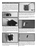
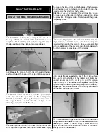
10. Install the throttle servo into the tray in the fuselage.

Drill a 1/16" [1.6mm] hole through each of the mounting
holes in the servo. Install and then remove a servo mounting
screw into each of the holes you have drilled. Apply a
couple of drops of thin CA into the holes to harden the
threads. After the glue has cured, install your servo.

11. Install a brass-screw lock connector and nylon retainer to

the servo arm. Slide it onto the pushrod wire, center the servo
and install the servo arm onto the servo. Then install the servo
screw into the servo and a 6-32 x 1/4" [6mm] socket head cap
screw into the screw-lock connector.

12. Cut the forward plywood pushrod support to fit

between the pushrod and the fuselage. Glue the two balsa
blocks to both sides of the support. Lightly sand the
fuselage where the support will be glued and then wipe the
area with rubbing alcohol. Glue the forward support to the
fuselage side and glue the rear support to the servo tray.

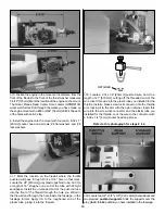
13. Assemble the fuel tank as shown. Included with the

fuel tank hardware is a 24" length of fuel tubing. This will be
used for attaching the tank to the carburetor and muffler
pressure tap. If you will be using a fuel valve (not included)
for filling the tank rather than filling the tank by removing the
line from the carburetor, install it in the fuel line following the
instructions included with the valve.

14. Install the fuel line included with the kit onto the tubes

extending from the fuel tank. Insert the lines and the fuel
tank into the fuselage. Hold the tank in place with a couple
of #64 rubber bands. Attach the carburetor line to the
carburetor. The vent line can be attached later when the
muffler is permanently installed.

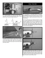
1. Use card stock as a template for making the cut out in

the cowl. Tape the card stock to the fuselage behind where
the cowl will be mounted. Mark the card stock where the
engine extends outside of the cowl. Cut that area out of the
card stock.

2. Remove the engine from the mount; slide the cowl onto the

fuselage. (If you are installing the O.S. .91 four stroke engine,
you can remove the rocker arm cover and the cowl will fit over
the engine without removing it.) Tape the cowl to the fuselage.
Trace the pattern from the card stock onto the cowling.

3. Remove the cowl from the fuselage. Cut out the area

you have marked. A high speed rotary tool works well for
this. Try to cut as closely to the area outlined as you can.You
will be making adjustments to the cut out as you continue
with the installation of the cowl. The goal now is to just be
able to slip the cowl over the engine and onto the fuselage.

4. Reinstall the engine onto the engine mount. Slide the

cowl over the engine and onto the fuselage.

Install the Cowl

15

Содержание Little Toni ARF

Страница 1: ...ly in new and unused condition to the place of purchase To make a warranty claim send the defective part or item to Hobby Services at this address Include a letter stating your name return shipping address as much contact information as possible daytime telephone number fax number e mail address a detailed description of the problem and a photocopy of the purchase receipt Upon receipt of the packa...

Страница 2: ...ear in the upper left corner of the page The Great Planes Little Toni is an excellent sport scale model and is eligible to fly in IMAA events The IMAA International Miniature Aircraft Association is an organization that promotes non competitive flying of giant scale models If you plan to attend an IMAA event obtain a copy of the IMAA Safety Code by contacting the IMAA at the address or telephone n...

Страница 3: ...fore we recommend that you get the assistance of an experienced pilot in your R C club for your first flights If you re not a member of a club your local hobby shop has information about clubs in your area whose membership includes experienced pilots In addition to joining an R C club we strongly recommend you join the AMA Academy of Model Aeronautics AMA membership is required to fly at AMA sanct...

Страница 4: ...er and a length For example 6 x 3 4 This is a number six screw that is 3 4 long Machine screws are designated by a number threads per inch and a length For example 4 40 x 3 4 This is a number four screw that is 3 4 long with forty threads per inch When you see the term test fit in the instructions it means that you should first position the part on the assembly without using any glue then slightly...

Страница 5: ... 2 x3 8 Wood Screw 4 8 32 x 1 1 4 SHCS 4 8 32 x 1 SHCS 4 4 40 x 1 8 SHCS 2 8 32 x 3 4 FH machine screw 4 3 32 Wheel Collar 1 5 32 Wheel Collar 6 1 1 4 tailwheel 1 074 wire Threaded 1 End 36 4 074 x 6 Pushrod Wire 2 4 40 x 12 thread wire 1 4 Lock Washer 4 4 flat washers 8 2 Flat Washers 12 8 Lock Washers 8 8 Flat Washers 8 Parts Layout Before starting to build take an inventory of this kit to make ...

Страница 6: ... Parts List that follows The fastest most economical service can be provided by your hobby dealer or mail order company Parts may also be ordered directly from Hobby Services but full retail prices and shipping and handling charges will apply Illinois and Nevada residents will also be charged sales tax To locate a hobby dealer visit the Hobbico web site at www hobbico com Choose Where to Buy at th...

Страница 7: ...ow up with a 11 blade to clean out the slots Hint If you have one use a high speed rotary tool to drill the holes 2 Use a sharp 11 blade to cut a strip of covering from the hinge slots in the wing and aileron 3 Cut five 3 4 x 1 19 x 25mm hinges from the CA hinge strip Snip off the corners so they go in easier 4 Test fit the ailerons to the wing with the hinges If the hinges don t remain centered s...

Страница 8: ...he servo arm is centered over the opening in the cover Clamp the blocks to the cover When the glue has cured remove the clamps 4 Mark the center of the hardwood blocks on the cover Drill a 1 16 1 6mm hole through the marks drilling through the blocks Install a 2 x 3 8 9mm wood screw into each of the holes tightening them against the cover 5 Attach the servo extension to the aileron servo Secure th...

Страница 9: ...8 16mm machine screws and the nylon mounting plate 10 Locate a 074 x 6 074 x 152mm pushrod wire threaded on one end Screw a nylon clevis onto the threaded end of the wire 20 full turns Install a silicone clevis keeper onto the clevis then install the clevis in the second hole from the end of the aileron control horn 11 Be sure the aileron servo is centered Enlarge the first hole in the servo arm w...

Страница 10: ...ith the dihedral anywhere between 5 3 4 and 6 1 2 146mm and 165mm 3 Set the wing aside allowing the glue to cure 4 Place the plywood wing bolt mounting plate in position on the bottom of the wing over the wing bolt holes Using a fine tip marker trace the outline of the plate onto the wing Use a sharp 11 hobby knife or use the Expert Tip that follows to cut the covering from the wing along the line...

Страница 11: ... likely cause the glue to get a white haze on the fuselage and stab Allow the plane to sit for approximately 5 minutes until the glue is completely cured 5 Cut six hinges three for each elevator half from the hinge material Install the two elevator halves using the same method used for the ailerons Once you are satisfied with the positioning of the elevators glue them in place with thin CA the sam...

Страница 12: ...2 Cut both axles to a length of 1 3 8 35mm A high speed rotary tool with a cut off wheel works well for this application 3 File a flat spot on the end of the axle A high speed rotary tool works well for this also 4 Insert a 6 32 set screw into a 5 32 4mm wheel collar Slide it onto the axle Slide the wheel onto the axle and then slide on another 5 32 wheel collar Screw a 6 32 x1 4 6mm socket head c...

Страница 13: ... the blind nut is pulled firmly against the firewall Remove the socket head cap screw Repeat this procedure for the remaining three blind nuts 4 Install the engine mount to the firewall using four each 8 32 x 1 1 4 32mm socket head cap screws 8 flat washers and 8 lock washers When installing the mount use your engine to determine the spacing needed for the mounting rails The following engine mount...

Страница 14: ...ll the un sanded end of the pushrod tube into the front of the firewall through the hole you drilled in the firewall and through the hole inside the fuselage in the fuselage former Apply CA to the roughened end of the plastic tube gluing it into the firewall 8 Locate a 074 x 36 914mm pushrod wire Cut it to a length of 21 533mm cutting off the threaded end of the wire Insert this wire into the plas...

Страница 15: ...ving the line from the carburetor install it in the fuel line following the instructions included with the valve 14 Install the fuel line included with the kit onto the tubes extending from the fuel tank Insert the lines and the fuel tank into the fuselage Hold the tank in place with a couple of 64 rubber bands Attach the carburetor line to the carburetor The vent line can be attached later when t...

Страница 16: ... the cowl tool 7 Look into the front of the fuselage and you will see four cowl mounting blocks glued inside The photo shows where the blocks are located Locate these blocks so when you mount the cowl you drill into the blocks The easiest way to find and mark the location of the blocks is to shine a high powered flash light inside the fuselage You should be able to see the shadowed outline of the ...

Страница 17: ... additional cut outs needed in the cowl for the needle valve muffler glow plug etc 1 Locate three 074 x 36 074 x 914mm pushrod wires threaded on one end Screw a nylon clevis onto the threaded end of the wires 20 full turns Install a silicone clevis keeper onto the clevises 2 Slide two of the wires with clevises attached into the openings closest to the back of the fuselage on both sides of the fus...

Страница 18: ...16 4 8mm Then cut off the excess pushrod wire Install a nylon Faslink to the wire and servo arm 7 Install the elevator servo into the servo tray Position it in line with the elevator pushrods Mount the servo using the same procedure used for the rudder servo 8 Make a bend in one of the elevator pushrod wires as shown 9 Screw a 6 32 x 1 4 6mm socket head cap screw with a small amount of threadlocke...

Страница 19: ...hin from the pilot figure 2 Trim the canopy on the molded cut lines The canopy can be glued to the fuselage or screwed in place If you look inside the fuselage you will see four plywood mounting blocks pre installed for this purpose Drill 1 16 1 6mm holes into the cowl and the blocks Hold the canopy in place with four 2 x 3 8 10mm screws and four flat washers If you choose to glue the canopy in pl...

Страница 20: ...the decal Apply the rest of the decals the same way 1 Turn on the transmitter and receiver and center the trims If necessary remove the servo arms from the servos and reposition them so they are centered Reinstall the screws that hold on the servo arms 2 With the transmitter and receiver still on check all the control surfaces to see if they are centered If necessary adjust the clevises on the pus...

Страница 21: ...ing amounts of weight on the bottom of the fuse over the firewall until the model balances Once you have determined the amount of weight required it can be permanently attached Note Do not rely upon the adhesive on the back of the lead weight to permanently hold it in place Over time fuel and This is where your model should balance for the first flights Later you may wish to experiment by shifting...

Страница 22: ...u can have a friend cycle your pack and note the capacity for you Carefully balance your propeller and spare propellers before you fly An unbalanced prop can be the single most significant cause of vibration that can damage your model Not only will engine mounting screws and bolts loosen possibly with disastrous effect but vibration may also damage your radio receiver and battery Vibration can als...

Страница 23: ...not throw anything into the propeller of a running engine Read and abide by the following Academy of Model Aeronautics Official Safety Code GENERAL 1 I will not fly my model aircraft in sanctioned events air shows or model flying demonstrations until it has been proven to be airworthy by having been previously successfully flight tested 2 I will not fly my model aircraft higher than approximately ...

Страница 24: ... Cycle your receiver battery pack if necessary and make sure it is fully charged 20 If you wish to photograph your model do so before your first flight 21 Range check your radio when you get to the flying field The Little Toni is a great flying model that flies smoothly and predictably The Little Toni does not however possess the self recovery characteristics of a primary R C trainer and should be...

Страница 25: ...ch lower the throttle while on the downwind leg Allow the nose of the model to pitch downward to gradually bleed off altitude Continue to lose altitude but maintain airspeed by keeping the nose down as you turn onto the crosswind leg Make your final turn toward the runway into the wind keeping the nose down to maintain airspeed and control Level the attitude when the model is on final approach Thi...

Страница 26: ...surprisingly simple setup Programming requires just 2 buttons and a data input lever Because the 6EXA is all digital you can lock in precise settings for everything That includes the digital trims which offer 241 discrete settings and a virtually unrestricted way to fine tune performance Besides essentials such as servo reversing and EPA on all six channels a trainer system and easy to read 40 seg...

Страница 27: ... This model belongs to Name Address City State Zip Phone number AMA number This model belongs to Name Address City State Zip Phone number AMA number Photocopy or cut out the ID tag and fill in the information needed Place one of these in your model We have provided a few extras ...

Страница 28: ...28 ...
Отзывы: