background image

❏ 

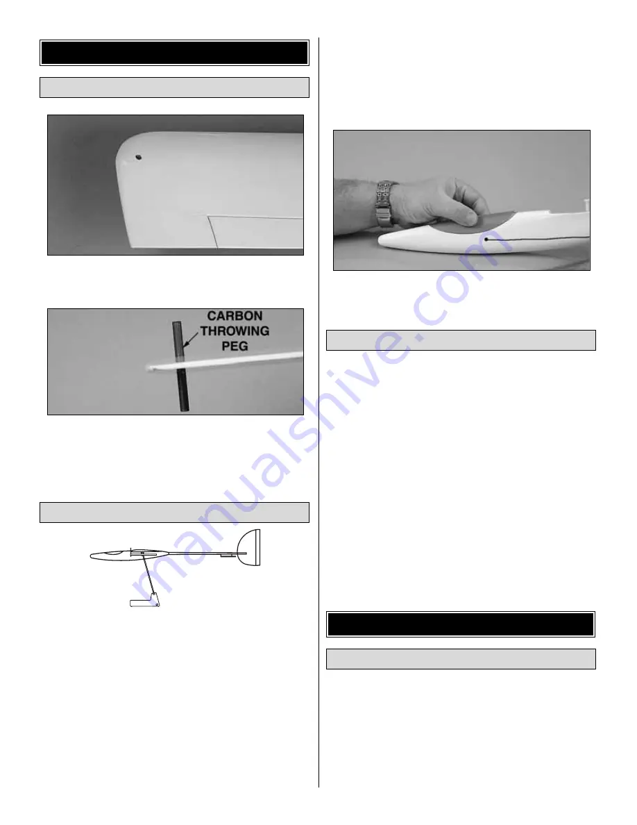
1. If you are right handed, remove the covering from the

hole in the left wing tip. If you are left handed, remove the
covering from the hole in the right wing tip.

❏ 

2. Push the 3/16" x 2" [5 x 50mm] carbon throwing peg

into the hole in the wing tip. Apply a small amount of epoxy
to the peg and twist the peg so that the epoxy goes into the
wing and the peg is centered vertically in the wing.

❏ 

1. Accurately mark the balance point on the bottom of the

wing on both sides of the fuselage. The balance point is
located 2-3/8" [60mm] back from the leading edge, at the
fuselage
. This is the balance point at which your model
should balance for your first flights. Later, you may wish to
experiment by shifting the balance up to 1/8" [3mm] forward
or 1/8" [3mm] back to change the flying characteristics.
Moving the C.G. forward will add some stability but it will
decrease the overall performance of the sailplane. Moving
the balance back makes the model more agile with a lighter
and snappier “feel” and improves the sailplane’s response to
air currents. In any case, please start at the location we
recommend and do not at any time balance your model
outside the recommended range.

❏ 

2. Temporarily place the battery and Rx in the fuse, and

mount the wing and canopy. Add the necessary weight to
make the plane balance at 2-3/8" [60mm]. We found the
best way to do this is to mix steel shot with epoxy and then
pour the correct amount into the nose. Work in small
increments of weight, double checking the CG each time.

❏ 

3. Route the antenna outside the fuselage and tape it to

the carbon fiber rod.

1. Use scissors or a sharp hobby knife to cut the decals
from the sheet.

2. Be certain the model is clean and free from oily fingerprints
and dust. Prepare a dishpan or small bucket with a mixture of
liquid dish soap and warm water—about one teaspoon of soap
per gallon of water. Submerse the decal in the soap and water
and peel off the paper backing.
Note: Even though the decals have a “sticky-back” and are not
the water transfer type, submersing them in soap & water allows
accurate positioning and reduces air bubbles underneath.

3. Position the decal on the model where desired. Holding the
decal down, use a paper towel to wipe most of the water away.

4. Use a piece of soft balsa or something similar to squeegee
remaining water from under the decal. Apply the rest of the
decals the same way.

❏ 

1. Turn on the transmitter and receiver and center the

trims. If necessary, remove the servo arms from the servos
and reposition them so they are centered. Reinstall the
screws that hold on the servo arms.

❏ 

2. With the transmitter and receiver still on, check all the

control surfaces to see if they are centered. If necessary, adjust
the clevises on the pushrods to center the control surfaces.

Check the Control Directions

GET THE MODEL READY TO FLY

Apply the Decals

CG 2-3/8" [60mm]  

Set the CG

Install the Throwing Peg

FINAL INSTALLATION & CG

11

Содержание Fling DL ARF

Страница 1: ...ct the buyer is advised to return this kit immediately in new and unused condition to the place of purchase To make a warranty claim send the defective Hobby Services part or item to Hobby Services at this address 3002 N Apollo Dr Suite 1 Champaign IL 61822 USA Include a letter stating your name return shipping address as much contact information as possible daytime telephone number fax number e m...

Страница 2: ...d in the Radio Equipment section of the manual Have a friend get a Fling DL ARF too and you can have first up last down contests or compete against each other trying to land the Fling DL ARF closest to a certain place a spot landing Have fun with your new Fling DL ARF For the latest technical updates or manual corrections to the Fling DL ARF visit the Great Planes web site at www greatplanes com O...

Страница 3: ...ke your time and follow the instructions to end up with a well built model that is straight and true This is a partial list of items required to finish the Fling DL ARF that may require planning or decision making before starting to build Order numbers are provided in parentheses 4 channel radio Y harness HCAM2500 or two 12 300mm extensions HCAM2100 utilizing a radio with flaperon mixing Great Pla...

Страница 4: ...dealer If a hobby shop is not available replacement parts may also be ordered from Tower Hobbies at www towerhobbies com or by calling toll free 800 637 6050 Parts may also be ordered directly from Hobby Services by calling 217 398 0007 or via facsimile at 217 398 7721 but full retail prices and shipping and handling charges will apply Illinois and Nevada residents will also be charged sales tax I...

Страница 5: ...lastic pull pull elevator turnaround 8 Decal sheet Before starting to build take an inventory of this kit to make sure it is complete and inspect the parts to make sure they are of acceptable quality If any parts are missing or are not of acceptable quality or if you need assistance with assembly contact Product Support When reporting defective or missing parts use the part names exactly as they a...

Страница 6: ... Use the pushrod and servo cover to position the servo NOTE If the CA is not spread thin enough it might wick into the servo and cause the gears to bind Do Not Use Thin CA 6 From the 1 16 x 6 1 6mm x 150mm pushrod make a pushrod with Z bends on each end that goes from the servo arm to the center of the hinge line 7 Cut the covering from the control horn slot on the bottom of the aileron Fit the pl...

Страница 7: ...ive amount of 30 minute epoxy Join the wing halves together Ensure that the left wing remains flat and that the right wing tip is 3 1 8 79mm from your work bench and can remain that way undisturbed until the epoxy has hardened Remove any excess epoxy with a paper towel and denatured alcohol being careful not to disturb the joint Hint Use masking tape to hold the wing together while the epoxy harde...

Страница 8: ...face Align the carbon support in the fin with the carbon fuse Check that the fin is perpendicular to the work surface If the fin is not perpendicular adjust the fin slot so that it is perpendicular Glue the fin to the fuse with thin CA DO NOT remove the covering from the fin 5 Drill four 1 16 1 6mm holes in the locations shown in the sketch 6 Slide the plastic elevator turnaround through the 1 8 3...

Страница 9: ... CA 9 Glue the stab to the fuse making sure it is aligned with the wing and that the TE of the elevator is 1 8 3mm in front of the fin 1 Trim the covering and slide the two sided plywood control horn through the rudder center it and then glue it with thin CA 2 Slide the single sided plywood control horn into the elevator and glue with thin CA 3 Install the aileron extensions under the servo tray A...

Страница 10: ...left side and cut it midway back on the fin 8 Slide the cut string that is on the right side of the fuse through the elevator turnaround 9 Plug the servos and battery into your receiver Turn on the transmitter to center the rudder and elevator servos 10 Tie the cut ends of the string to the elevator control horn The strings need to have some tension on them and the elevator needs to be aligned wit...

Страница 11: ...mix steel shot with epoxy and then pour the correct amount into the nose Work in small increments of weight double checking the CG each time 3 Route the antenna outside the fuselage and tape it to the carbon fiber rod 1 Use scissors or a sharp hobby knife to cut the decals from the sheet 2 Be certain the model is clean and free from oily fingerprints and dust Prepare a dishpan or small bucket with...

Страница 12: ... on you should be able to walk at least 100 feet away from the model and still have control Have an assistant stand by your model and while you work the controls tell you what the control surfaces are doing If the control surfaces do not respond correctly do not fly Find and correct the problem first Look for loose servo connections or broken wires corroded wires on old servo connectors poor solde...

Страница 13: ... aircraft are allowed at or in the front of the flight line Intentional flying behind the flight line is prohibited 4 I will operate my model using only radio control frequencies currently allowed by the Federal Communications Commission 5 I will not knowingly operate my model within three miles of any pre existing flying site except in accordance with the frequency sharing agreement listed in the...

Страница 14: ...sible for a good high launch Do not use too much arm in this section Just let the rotation of your torso speed the plane up Release Foot position 5 By this time in the launch the plane will be trying to climb on its own Just release your fingers and let the plane fly out of your hand Try to release it directly into the wind Recovery Foot position 6 This last step is just to catch your balance and ...

Страница 15: ...the controls when you have to Watch the sailplane carefully and it will tell you what it is encountering When the sailplane flies directly into a thermal it will either start rising or stop sinking Either case is reason enough to start circling especially in a contest where every second counts Fly straight ahead until you feel like you are in the strongest lift fly a couple of seconds farther so y...

Страница 16: ...o try to fly in The faster the wind is blowing the stronger the lift and turbulence will be To fly off a slope stand near the edge and throw the sailplane nose down into the wind As the sailplane flies out into the band of lift it will begin to gain altitude Turn and fly parallel to the slope and make all of your turns into the wind especially when you are close to the slope You will be surprised ...

Отзывы: