


❏
1. Check the C.G. according to the measurements
provided in the manual.
❏
2. Be certain the battery and receiver are securely
mounted in the fuse.
❏
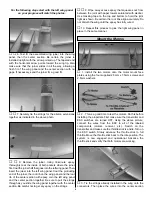
3. Extend your receiver antenna and make sure it has a
strain relief inside the fuselage to keep tension off the solder
joint inside the receiver.
❏
4. Balance your model
laterally as explained in
the instructions.
❏
5. Use threadlocking compound to secure critical
fasteners such as the set screws that hold the wheel axles
to the struts, screw-lock pushrod connectors, etc.
❏
6. Add a drop of oil to the axles so the wheels will turn freely.
❏
7. Make sure all hinges are securely glued in place.
❏
8. Reinforce holes for wood screws with thin CA
where appropriate (servo mounting screws, cowl mounting
screws, etc.).
❏
9. Confirm that all controls operate in the correct
direction and the throws are set up according to the manual.
❏
10 Make sure that all servo arms are secured to the
servos with the screws included with your radio.
❏
11. Secure connections between servo wires and
Y-connectors or servo extensions and the connection between
your battery pack and the on/off switch with vinyl tape, heat
shrink tubing or special clips suitable for that purpose.
❏
12. Make sure any servo extension cords you may have
used do not interfere with other systems (servo arms,
pushrods, etc.).
❏
13. Place your name, address, AMA number and
telephone number on or inside your model.
❏
14. If you wish to photograph your model, do so before
your first flight.
❏
15. Range check your radio when you get to the flying field.
The Great Planes DC-3 EP ARF is a great-flying model that
flies smoothly and predictably. The Great Planes DC-3 EP
ARF does not, however, possess the self-recovery
characteristics of a primary R/C trainer and should be flown
only by experienced R/C pilots.
If you are not used to using the rudder to coordinate turns,
this is one model where you should start doing so. The
DC-3 EP has a large wingspan with a relatively short
fuselage. As a result, the adverse yaw produced when the
ailerons alone are used to turn is much more pronounced
than you may be accustomed to. In addition, the increased
drag caused by the adverse yaw will slow the model and
cause the nose to drop slightly. Using coordinated rudder
(right rudder with right aileron) will give much cleaner and
better looking turns. Of course, this is a good control
technique for any model.
Due to the small wheel size of the DC-3 EP, rise off ground
(ROG) takeoffs are only possible from a smooth surface. If
you are flying from a grass field, the DC-3 EP can be safely
and easily hand-launched. Do not attempt to do so by
yourself. Have an assistant launch the model in a level or
slightly nose high attitude, with the wings level. It is not
necessary to throw the model into the air. Simply take a few
steps while gently pushing the model into the air. Allow the
model to accelerate before climbing or turning. Always
launch the model into the wind.
Before you get ready to takeoff, see how the model handles
on the ground by doing a few practice runs at low speeds on
the runway. Hold “up” elevator to keep the tail wheel on the
ground. If necessary, adjust the tail wheel so the model will
roll straight down the runway.
Takeoff
CAUTION (THIS APPLIES TO ALL R/C AIRPLANES): If,
while flying, you notice an alarming or unusual sound
such as a low-pitched “buzz,” this may indicate control
surface flutter. Flutter occurs when a control surface (such
as an aileron or elevator) or a flying surface (such as a
wing or stab) rapidly vibrates up and down (thus causing
the noise). In extreme cases, if not detected immediately,
flutter can actually cause the control surface to detach or
the flying surface to fail, thus causing loss of control
followed by an impending crash. The best thing to do
when flutter is detected is to slow the model immediately
by reducing power, then land as soon as safely possible.
Identify which surface fluttered (so the problem may be
resolved) by checking all the servo grommets for
deterioration or signs of vibration. Make certain all
pushrod linkages are secure and free of play. If it fluttered
once, under similar circumstances it will probably flutter
again unless the problem is fixed. Some things which can
cause flutter are; Excessive hinge gap; Not mounting
control horns solidly; Poor fit of clevis pin in horn; Side-
play of wire pushrods caused by large bends; Excessive
free play in servo gears; Insecure servo mounting; and
one of the most prevalent causes of flutter; Flying an over-
powered model at excessive speeds.
FLYING
During the last few moments of preparation your mind may
be elsewhere anticipating the excitement of the first flight.
Because of this, you may be more likely to overlook certain
checks and procedures that should be performed before
the model is flown. To help avoid this, a checklist is provided
to make sure these important areas are not overlooked.
Many are covered in the instruction manual, so where
appropriate, refer to the manual for complete instructions.
Be sure to check the items off as they are completed.
CHECKLIST
19