GREAT PLANES Douglas DC-3 Скачать руководство пользователя страница 11

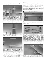
2. Place the wing onto the fuselage and secure it in place

with two 4mm x 22mm wing bolts and 4mm flat washers.
Trial fit the wing fairing into place as shown. When satisfied
with the fit, glue the fairing into place using thin CA.

1. Locate the 1/8" [3.2mm] ply servo trayaft former and

mid former. Glue the aft and mid formers to the servo tray
as shown above.

2. Locate the rear of the servo tray 12 inches from the nose

of the fuselage as shown in the photo above. Mark the
locations where the tray will be glued to the fuselage. Remove
the tray and sand the locations with 220-grit sandpaper. Clean
the area with a paper towel and rubbing alcohol. Glue the
servo tray into position with epoxy or medium CA.

3. Trial fit the battery tray into place as far forward as

possible in the nose of the fuselage. The tray should be 1-3/4"
[44.5mm] below the hatch opening at the rear edge. When
satisfied with the fit, glue the tray into place with epoxy.
Important: The battery tray should fit into the fuselage
without pushing the sides outwards. Carefully check that the
battery tray does not cause the fuselage sides to flex
outwards as it is inserted into place. Sand the sides of the tray
if necessary. If the sides flex outwards, the battery hatch will
not fit properly.

Install the Formers

ASSEMBLE THE  FUSELAGE

IMPORTANT NOTES ABOUT

WORKING WITH FIBERGLASS

If you have never worked with fiberglass there are a few
basic things you should be aware of:

• When you are cutting into fiberglass, be sure you are
cutting the correct place. Unlike wood, you are not able to
go back and easily fix a mistake.

• Whenever you are gluing a part to the inside of fiberglass
it is important to roughen the inside surface of the fiberglass
with 220-grit sandpaper and then wipe the area with
rubbing alcohol. The molding process leaves a waxy
residue that can prevent a good bond between the glue and
the parts being glued.

Warning: The fuselage included in this kit is made of
fiberglass, the fibers of which may cause eye, skin
and respiratory tract irritation. Never blow into a part
to remove fiberglass dust, as the dust will blow back
into your eyes. Always wear safety goggles, a particle
mask and rubber gloves when grinding, drilling or
sanding fiberglass parts. Vacuum the parts and the
work area thoroughly after working with fiberglass.

11

Содержание Douglas DC-3

Страница 1: ...sed to return this kit immediately in new and unused condition to the place of purchase To make a warranty claim send the defective part or item to Hobby Services at the address below Hobby Services 3...

Страница 2: ...ts Information about R C clubs and instructors is provided later in this manual For the latest technical updates or manual corrections to the DC 3 EP ARF visit the Great Planes web site at www greatpl...

Страница 3: ...w modelaircraft org This is a partial list of items required to finish the DC 3 EP ARF that may require planning or decision making before starting to build Order numbers in parentheses are provided f...

Страница 4: ...pplicator tips GPMR6033 Curved tip canopy scissors for trimming plastic HCAR0667 When you see the term test fit in the instructions it means that you should first position the part on the assembly wit...

Страница 5: ...h 15 1 8 3 2mm Ply Servo Tray 16 51 5mm Main Wheels 2 17 1 8 3 2mm Ply Mid Former Servo Tray 18 1 8 3 2mm Ply Aft Former Servo Tray 19 1 8 3 2mm Ply Wing Joiners 4 20 Fiberglass Nose Hatch Strips 4 21...

Страница 6: ...s If you need assistance locating a dealer to purchase parts visit www greatplanes com and click on Where to Buy If this kit is missing parts contact Product Support Replacement Parts List Order Numbe...

Страница 7: ...e wing wire outlets 2 gear openings 2 wing bolt holes 2 servo openings 2 on left and right panels not pictured 4 There are two strings inside the wing center section that have the ends taped to each r...

Страница 8: ...with the center section Be careful not to get any epoxy on the strings 9 Wipe away excess epoxy that squeezes out from between the joint with paper towels saturated with alcohol Use masking tape on t...

Страница 9: ...s a good quality carpet tape 2 Assemble the propeller shaft extension propeller and the propeller adapter as shown in the above photo Place the rubber propeller adapter into the propeller and press it...

Страница 10: ...the screws then screw them into place Remove the screws and harden the holes with a few drops of thin CA After the CA hardens reinstall the servo and screws 4 Mount the nylon control horn on the aile...

Страница 11: ...attery tray does not cause the fuselage sides to flex outwards as it is inserted into place Sand the sides of the tray if necessary If the sides flex outwards the battery hatch will not fit properly I...

Страница 12: ...lue them into place Also glue the outer tubes at the exit points at the rear of the fuselage 4 Assemble the elevator and rudder servos as shown in the above photo using the grommets brass eyelets and...

Страница 13: ...ends are the same distance Mark the stab at the leading and trailing edges with a fine tip marking pen Remove the stab from the fuselage Do not glue the stab into place yet 4 The two elevator halves...

Страница 14: ...glue on the stab or on the fuselage When you have the elevators in place with no gaps between the stab and elevators place six drops of thin CA on both sides of each hinge and let it cure Do not use a...

Страница 15: ...elage using two 2 5mm x 9 5mm flanged Phillips head screws as shown in the photo above Drill 1 16 1 6mm pilot holes for the screws Harden the holes with thin CA 7 Mount the 25mm tail wheel with a 2mm...

Страница 16: ...mained centered Adjust if necessary Use a Great Planes AccuThrow or a ruler to accurately measure and set the control throw of each control surface as indicated in the chart that follows If your radio...

Страница 17: ...u lift the model by the engine propeller shaft and the bottom of the fuse under the TE of the fin Do this several times 2 If one wing always drops when you lift the model it means that side is heavy B...

Страница 18: ...hot Do not touch them during or right after operation The electric motors and battery used in your DC 3 EP ARF are very powerful and the spinning propellers have a lot of momentum therefore if you to...

Страница 19: ...ROG takeoffs are only possible from a smooth surface If you are flying from a grass field the DC 3 EP can be safely and easily hand launched Do not attempt to do so by yourself Have an assistant laun...

Страница 20: ...el stalls This model does not slow rapidly on final approach so a low dragged in approach may be needed Always land into the wind Due to the small wheel size the model may start to nose over Gradually...

Отзывы: