background image

1520F, 2020F, 2420F, 1510HDF, & 

2010HDF 

8/17/2020

4

Practice Safe Maintenance

Understand procedure before doing work. Use

proper tools and equipment. Refer to this man

-

ual for additional information.

Work in a clean, dry area.
Lower  the  drill,  put  tractor  in  park,  turn  off

engine,  and  remove  key  before  performing

maintenance.

Make sure all moving parts have stopped and

all system pressure is relieved.

Allow drill to cool completely.
Disconnect  battery  ground  cable  (-)  before

servicing  or  adjusting  electrical  systems  or

before welding on drill.

Inspect all parts. Make sure parts are in good

condition and installed properly.

Remove buildup of grease, oil or debris.
Remove all  tools  and unused parts  from  drill

before operation.

Prepare for Emergencies

Be prepared if a fire starts.
Keep a first aid kit and fire extinguisher handy.
Keep  emergency  numbers  for  doctor,  ambu

-

lance,  hospital  and  fire  department  near

phone.

Wear Protective Equipment

Wear protective clothing and equipment.
Wear  clothing and equipment appropriate for

the job. Avoid loose-fitting clothing.

Because  prolonged  exposure  to  loud  noise

can cause hearing impairment or hearing loss,

wear suitable hearing protection such as ear

-

muffs or earplugs.

Because operating equipment safely requires

your full attention, avoid wearing radio head

-

phones while operating machinery.

911

OFF

Содержание 1510HDF

Страница 1: ...hen you see this symbol the subsequent instructions and warnings are serious follow without exception Your life and the lives of others depend on it Manufacturing Inc www greatplainsmfg com Operator s Manual 1520F 2020F 2420F 1510HDF 2010HDF 15 20 and 24 3 Point Drills 288 196M Copyright 2006 Printed 2 28 2006 24137 ...

Страница 2: ...ions 13 Owner Assistance 14 Preparation and Setup 15 Prestart Checklist 15 Hitching Tractor to Drill 15 Hydraulic Hose Hookup 16 Leveling the Drill 17 Operating Instructions 21 Prestart Checklist 21 Field Operation 22 Opener Operation 23 Marker Operation 23 Transporting 23 Transporting with Markers 24 Parking 24 Adjustments 25 Side Gauge Wheels for 20 Series Openers 25 20 Series Openers 26 Opener ...

Страница 3: ... Aware of Signal Words Signal words designate a degree or level of haz ard seriousness DANGER indicates an imminently hazardous sit uation which if not avoided will result in death or serious injury This signal word is limited to the most extreme situations typically for machine components that for functional purposes cannot be guarded WARNING indicates a potentially hazardous situ ation which if ...

Страница 4: ...ll bystanders away from machine during operation Shutdown and Storage Lower drill put tractor in park turn off engine and remove the key Secure drill using blocks and supports pro vided Detach and store drill in an area where chil dren normally do not play Use Safety Lights and Devices Slow moving tractors and towed implements can create a hazard when driven on public roads They are difficult to s...

Страница 5: ... times the weight of towing vehicle Carry reflectors or flags to mark drill in case of breakdown on the road Keep clear of overhead power lines and other obstructions when transporting Avoid High Pressure Fluids Escaping fluid under pressure can penetrate the skin causing serious injury Avoid the hazard by relieving pressure before disconnecting hydraulic lines Use a piece of paper or cardboard NO...

Страница 6: ...ts are in good condition and installed properly Remove buildup of grease oil or debris Remove all tools and unused parts from drill before operation Prepare for Emergencies Be prepared if a fire starts Keep a first aid kit and fire extinguisher handy Keep emergency numbers for doctor ambu lance hospital and fire department near phone Wear Protective Equipment Wear protective clothing and equipment...

Страница 7: ...rawbar Use a chain with a strength rating equal to or greater than the gross weight of towed machinery Attach chain to tractor drawbar support or other specified anchor location Allow only enough slack in chain to permit turning Replace chain if any links or end fittings are broken stretched or damaged Do not use safety chain for towing Tire Safety Tire changing can be dangerous and should be perf...

Страница 8: ...e running Do not dismount a moving tractor Dismount ing a moving tractor could cause serious injury or death Do not stand between the tractor and drill during hitching Keep hands feet and clothing away from power driven parts Wear snug fitting clothing to avoid entangle ment with moving parts Watch out for wires trees etc when folding markers or raising drill Make sure all persons are clear of wor...

Страница 9: ...your Great Plains dealer Refer to this section for proper decal place ment When ordering new parts or components also request corresponding safety decals To install new decals 1 Clean the area on which the decal is to be placed 2 Peel backing from decal Press firmly on surface being careful not to cause air bubbles under decal 818 003C Slow Moving Vehicle Label 838 266C Red Reflectors Reflectors o...

Страница 10: ...18 339C High Pressure Hazard 838 265C Amber Reflectors Reflector on both ends of drill four reflectors total 18262 19189 838 267C Decal Reflectors Daytime Reflectors on inside ends and off center on walk boards next to red reflectors four reflectors total ...

Страница 11: ...ty Information 818 587C General Instructions 818 590C Crushing Hazard 18262 18262 18262 19195 838 102C Falling Hazard WARNING To avoid serious injury or death Watch your step when climbing ladder or walking on walkboard 838 102C ...

Страница 12: ...1520F 2020F 2420F 1510HDF 2010HDF 8 17 2020 10 19197 18270 818 855C Tire Pressure 818 229C Amber Reflector Reflector on each optional marker 818 398C Falling Hazard 19197 ...

Страница 13: ...ction of each optional marker four decals total 818 337C Excessive Speed Hazard 18270 21641 818 752C Tire Pressure 21641 WARNING EXCESSIVE SPEED HAZARD To Prevent Serious Injury or Death Do NOT exceed 20 mph maximum transport speed Loss of vehicle control and or machine damage can result 818 337C Rev B ...

Страница 14: ...ft and 24 ft 3 point drills are equipped with HD 10 Series and 20 Series open ers The HD 10 Series Opener is outfitted with heavy duty parallel arm openers The 20 Series Opener is outfitted with side depth control open ers These openers are staggered for easy residue flow Opener depth can be adjusted Intended Usage Use the drill to seed production agriculture crops only Do not modify the drill for...

Страница 15: ...op performance Definitions The following terms are used throughout this manual Refer to Figure 1 Right hand and left hand as used in this manual are determined by facing the direction the ma chine will travel while in use unless otherwise stated IMPORTANT A crucial point of information re lated to the preceding topic For safe and cor rect operation read and follow the directions provided before co...

Страница 16: ...Mfg Inc Service Department PO Box 5060 Salina KS 67402 5060 Owner Assistance If you need customer service or repair parts con tact a Great Plains dealer They have trained personnel repair parts and equipment specially designed for Great Plains products Refer to Figure 2 Yourmachine sparts were speciallydesigned and should only be replaced with Great Plains parts Always use the serial and model num...

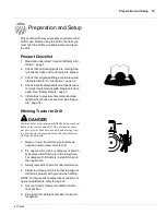
Страница 17: ...ied See Appen dix page 56 Hitching Tractor to Drill DANGER You may be severely injured or killed by being crushed between the tractor and drill Do not stand or place any part of your body between drill and moving trac tor Stop tractor engine and set park brake before in stalling the hitch pin 1 Raise or lower tractor three point arms as needed and pin lower arms to drill 2 Pin upper arm to drill F...

Страница 18: ...ctor outlets Hoses that go to the same remote valve are marked with the same color To distinguish hoses on the same hydraulic cir cuit refer to plastic hose holder Hose under extended cylinder symbol feeds cylinder base ends Hose under retracted cylinder symbol feeds cylinder rod ends Color Hydraulic Function Orange Marker Cylinders Figure 3 Hydraulic Hose Label 17641 ...

Страница 19: ...8 inches between pin centers to achieve the 24 inch dimension mentioned above When adjusting the linkage length re member Lengthening linkage raises drill Shortening linkage lowers drill 3 Level drill with top three point link Refer to Figure 6 NOTE When drill is level parallel links will be run ning slightly uphill towards the front The 1 inch dimension shown is a general dimen sion that will var...

Страница 20: ... inch dimension mentioned above When adjusting the turnbuckle length remember Lengthening turnbuckle raises drill Shortening turnbuckle lowers drill 4 After adjusting both turnbuckles to the same length tighten jam nuts 5 Level drill with top three point link Refer to Figure 9 NOTE When drill is level parallel links will be run ning slightly uphill towards the front The 1 inch dimension shown is a...

Страница 21: ...etween pin centers to achieve the 26 inch dimension mentioned above When adjusting the linkage length re member Lengthening linkage raises drill Shortening linkage lowers drill 3 Level drill with top three point link Refer to Figure 12 NOTE When drill is level parallel links will be run ning level or slightly uphill towards the front The 1 inch dimension shown is a general dimen sion that will var...

Страница 22: ...ension mentioned above When adjusting the turnbuckle length remember Lengthening turnbuckle raises drill Shortening turnbuckle lowers drill 3 Level drill with top three point link Refer to Figure 4 NOTE When drill is level parallel links will be running slightly uphill towards the front The 1 inch dimension shown is a general di mension that will vary with planting conditions IMPORTANT Make sure t...

Страница 23: ...istance from a doctor that is familiar with this type of injury Foreign fluids in the tissue must be surgically removed within a few hours or gangrene will result 1 Carefully read Important Safety Information page 1 2 Lubricate drill as indicated under Lubrica tion page 52 3 Check all tires for proper inflation See Ap pendix page 56 4 Check all bolts pins and fasteners Torque as shown in Appendix ...

Страница 24: ... rate as explained under Seeding Rate Adjustments page 15 3 Checkthat seed cup door handles are set the same across the drill Refer to Seeding Rate Adjustments page 15 NOTE If you notice excessive cracking on large seeds adjust all seed cup doors to a wider set ting Use the widest setting only for seed cup clean out 4 Load box with clean seed 5 Record acremeter readout Subtract inital reading from...

Страница 25: ...left stays folded 2 Reverse lever Right folds left stays fold ed 3 Activate lever Left unfolds right stays folded 4 Reverse lever Left folds up right stays folded 5 Sequence repeats You can adjust marker folding speed Refer to MarkerAdjustments page 40 and adjust folding speed to a safe rate Folding markers at high speed can damage markers Transporting WARNING Towing the drill at high speeds or wi...

Страница 26: ... quired Road rules Comply with all federal state and lo cal safety laws when traveling on public roads Refer to Figure 17 Clearance Remember that the drill is wider than the tractor Allow safe clearance Fold up walk board ladder for maximum clearance Transporting with Markers Always transport markers in the folded position Parking For information on long term storage refer to Storage page 51 WARNI...

Страница 27: ...o clock to 7 o clock Use this as the starting point for adjustment 4 Move wheel arm in so side gauge wheel contacts row unit disk Tighten hex head bolt 1 to clamp arm around bushing and shank 5 Check wheel to disk contact at 2 planting depth Lift wheel and arm When let go wheel should fall freely If wheel does not contact disk at bottom to area where blade leaves contact with soil move hex ad just...

Страница 28: ... seed trench and maintain proper soil firming over seed Ex cessive opener down force will lead to premature wear on opener components Refer to Figure 22 To adjust down pressure use adjustment tool stored under walkboard Position tool in holes on spring mounting plates and pull down Move the adjustment cam to the new setting Refer to Figure 23 Minimum and maximum settings are indicated by position ...

Страница 29: ...r to Figure 26 Press wheels are attached to each opener body The press wheels close the seed trench and gen tly press soil over seed An adjustable spring in the press wheel mecha nism creates the down pressure needed to close the seed trench The amount of force needed will vary with field conditions To adjust move adjustment handle For less down pressure move handle forward toward drill For more d...

Страница 30: ...s are spring loaded and do not require adjusting In some wet and sticky conditions the wheels may accumulate soil Refer to Figure 28 NOTE Side gauge wheel and seed meter is re moved for clarity To lock up Seed Lok wheels raise drill Rotate lock up handle 1 90 degrees down on top of opener body Push up on Seed Lok wheel 2 until wheel arm latches up CAUTION Opener disk blades may be sharp Use cautio...

Страница 31: ...d planting in tire tracks Use only enough down pressure to cut the seed trench and maintain proper soil firming over seed Excessive opener down force will lead to prema ture wear of opener components Excessive down force will also cause uneven seed depth Refer to Figure 39 To adjust down pressure use adjustment wrench stored under the walkboard or a 1 1 8 open end wrench Position wrench on the nut...

Страница 32: ... trench and gently press soil over seed To provide consistent soil firming press wheels are free to move down from normal operating position This maintains pressing action even if opener disks encounter obstructions or hard soil Refer to Figure 41 Set opener seeding depth by adjusting T handles To adjust first raise openers slightly then lift and slide T handles on top of openers as shown Ad just ...

Страница 33: ...eed trench and press soil over the seed To move the wheels 4 in toward the center of the trench remove one of the 1 4 bushings 2 next to the press wheel arm and position it under the head of the bolt 1 On wider row spacings the closing wheels 4 can be moved outward by plac ing two 1 4 spacers 2 inside next to the press wheel arm 3 Figure 42 Double V Press Wheel 23428 ...

Страница 34: ...ne by placing a small block below the disc blades and setting the drill down upon it 3 Insert locking pin through both holes and low er the opener allowing the pin to rest on the top of the lower parallel arm NOTE Do not pin the opener while it is in the low ered position If the pin is inserted below the par allel arm it WILL damage opener soon after planting begins Refer to Figure 44 When pin is ...

Страница 35: ... drill Level drill with top three point link NOTE Lowering the drill increases the risk of open er damage on rocks or obstructions Dual Gauge Wheels Refer to Figure 46 1 Loosen jam nut near top clevis of each gauge wheel turnbuckle NOTE Jam nut is left hand threaded 2 Make sure upper clevis 2 is in upper mount hole as shown for 20 series and in the lower mount hole for HD 10 series 3 Set turnbuckl...

Страница 36: ...nstall drive sprockets for the drive type for your desired seeding rate For correct drive type refer to seed rate charts be ginning on page 18 The charts list drive types as 1 2 3 or 4 Refer to the following table for the cor rect sized sprocket for each drive type Drive Type Driver Driven Speed Type 1 14 Tooth 44 Tooth Slowest Type 2 24 Tooth 36 Tooth Two Times Faster Than Type 1 Type 3 24 Tooth ...

Страница 37: ...l seed drops to ground from all three cups 5 Place a container under the three seed tubes to gather seed as it is metered 6 Turn drive gauge wheel for one acre Refer to the chart on the next page for the exact num ber of tire revolutions to equal one acre Check that three seed cups have plenty of seed coming into them 7 Weigh metered seed Subtract initial weight of empty container Divide by three ...

Страница 38: ...32 268 38 225 9 1 2 26 260 10 18 365 24 268 28 229 10 19 346 25 257 15 12 365 16 268 19 225 15 13 337 17 252 20 214 19 13 260 20 9 365 12 268 14 229 20 10 329 30 6 365 8 268 10 214 36 6 297 38 6 282 40 6 268 Twin Row 30 beds 12 365 16 268 20 214 Twin Row 36 beds 12 297 16 223 Twin Row 38 beds 12 282 16 211 Twin Row 40 beds 12 268 16 201 Twin Row 30 W S 19 346 25 257 29 221 15 Skip Row 14 268 NOTE ...

Страница 39: ...0 Buck Wheat Drive Type 3 Based on 48 bu Row Spacing 6 0 11 21 29 42 52 65 78 92 107 123 136 150 165 180 195 209 224 240 242 245 7 0 10 18 25 36 45 56 67 79 92 106 116 129 142 154 168 179 192 205 207 210 7 5 0 9 17 24 34 42 52 62 74 85 99 109 120 132 144 156 167 179 192 194 196 8 0 8 16 22 31 39 49 59 69 80 92 102 113 124 135 147 157 168 180 181 183 10 0 7 13 18 25 31 39 47 55 64 74 81 90 99 108 1...

Страница 40: ...0 0 1 2 3 8 6 3 8 9 11 7 14 4 17 0 19 7 22 4 27 1 27 5 30 1 32 7 35 2 38 0 40 1 42 4 44 2 45 3 46 2 7 5 0 0 1 1 3 6 5 9 8 3 10 9 13 5 15 9 18 4 20 9 25 3 25 7 28 1 30 5 32 9 35 4 37 5 39 5 41 2 42 3 43 1 8 0 0 1 1 3 3 5 5 7 8 10 2 12 6 14 9 17 2 19 6 23 7 24 1 26 3 28 6 30 8 33 2 35 1 37 1 38 6 39 7 40 4 10 0 0 0 8 2 7 4 4 6 2 8 2 10 1 11 9 13 8 15 7 19 0 19 3 21 1 22 9 24 7 26 6 28 1 29 7 30 9 31...

Страница 41: ... 73 86 109 124 142 161 181 200 221 240 261 278 304 324 347 347 348 10 0 11 22 40 58 69 87 99 114 128 145 160 177 192 209 223 243 260 278 278 278 Sun flowers Drive Type 1 Based on 28 bu Row Spacing 6 0 0 2 4 6 8 11 13 15 18 20 23 25 27 30 32 34 36 38 39 41 7 0 0 2 4 5 7 9 11 13 15 17 19 21 23 25 27 29 31 33 34 35 7 5 0 0 2 3 5 7 9 10 12 14 16 18 20 22 24 26 27 29 31 32 33 8 0 0 2 3 5 6 8 10 12 13 1...

Страница 42: ...his type of injury Foreign fluids in the tissue must be surgically removed within a few hours or gangrene will result Check that tractor hydraulic reservoir is full 1 With both markers lowered into field position loosen hydraulic hose fittings at rod and base ends of marker cylinders If applicable loosen fittings on back side of sequence valve IMPORTANT Never bleed an O ring fitting In stead bleed...

Страница 43: ...ed 1 and one for lowering speed 2 Identify adjustment screws by mark ings stamped in valve body With tractor idling at a normal operating speed adjust marker folding to a safe speed Turn adjust ment screws clockwise to decrease folding speed and counterclockwise to increase folding speed Excessive folding speed could damage markers and void the warranty After adjusting the folding speed tighten ja...

Страница 44: ...skips in your marker line Correct this condition by lengthening chain one or two links at clevis 2 2 Folding Slack Fold marker Use full threaded adjustment bolt 1 to take slack out of chain while marker is folded Extend bolt until there is no chain slack Lock bolt in this position by tight ening nuts 3 on either side of upright channel 4 Transport Carrier When marker is folded the second section s...

Страница 45: ...3 Adjustments Marker Width Refer to Figure 83 To adjust marker width loosen jam nuts 1 and 1 2 inch set screws 2 Move marker disk tube in or out to get the proper dimension 19204 Figure 83 Marker Width Adjustment ...

Страница 46: ...eel and seed meter is re moved for clarity To lock up Seed Lok wheels raise drill Rotate lock up handle 1 90 degrees down on top of opener body see insert Push up on Seed Lok wheel 2 until wheel arm latches up CAUTION Opener disk blades may be sharp Use caution when making adjustments in this area To unlock Seed Lok wheels pull up lock up handle 1 Seed lok is spring loaded so it will snap back int...

Страница 47: ... On 20 Series Open ers refer to Opener Down Pressure Adjustments page 26 Actual metering rate is different than desired Check tire pressure Proper inflation is listed on the Tire Inflation Chart Appendix page 57 Check tire size Proper size is 9 5L x 15 for 15 foot drills and 11L x 15 for 20 foot drils and 24 foot drills Regularly clean seed treatment from seed cups Check drill box setting Refer to...

Страница 48: ...l drill If using pull package or hitch equipped with a telescoping top link increase opener spring pressure to rock drill forward Refer to Opener Down Pressure Adjustments page 26 Gauge wheel leans to left or right Realign brackets where gauge wheel is attached to main frame by adjusting u bolts Check if axle bearings are securely attached to gauge wheel arm Hydraulic marker functioning improperly...

Страница 49: ... hydraulic lines and fittings before applying pressure Fluid escaping from a very small hole can be almost invisible Use pa per or cardboard not body parts and wear heavy gloves to check for suspected leaks If injured seek medical assistance from a doctor that is familiar with this type of injury Foreign fluids in the tissue must be surgically removed within a few hours or gangrene will result 1 A...

Страница 50: ...chine washer 8 between the side gauge wheel 2 and the wheel arm 3 There must be three flat washers 1 and one machine washer 8 between the wheel bearing and arm with the machine washer 8 next to the arm There should be three flat wash ers 1 and one lock washer 9 on the outside the wheel When installed the wheel should turn freely and not hit the arm at the curve Do not add any more washers than nec...

Страница 51: ...blades Bring paper down until it stops In lower gap place another piece of paper Bring paper up until it stops The distance must be between 1 2 and 1 3 4 inches Add or remove shims as needed to get the correct contact point CAUTION Disk edges are sharp Be careful when working in this area Figure 101 Opener Disks Contact Point 1 2 inch to 1 3 4 inches 18412 20 Series Opener Disk Spreader Refer to F...

Страница 52: ...e loose ness is required for proper operation Refer to Figure 103 1 With unit raised check blade spreader 1 for wear Replace spreader if it is 1 2 inches wide or narrower To replace remove disk blade 3 Drive out roll pins 2 and install new spreader 2 When reinstalling disk blades put two shims 4 be tween bearing and shank on each blade Tighten bolts 22839 Figure 103 Spreaders and Scrapers ...

Страница 53: ...e Store the drill where children do not play If possi ble store the drill inside for longer life 1 Unload seed box Place tarp under drill or a bucket under each seed meter Use a large bucket to empty box as much as possible Make sure sliding seed tubes are in the open position Open seed meter clean out to empty seed out of sliding seed tube and meter 2 Thoroughly clean seed and seed treatment resi...

Страница 54: ...0 Multipurpose spray lube Multipurpose grease lube Multipurpose oil lube Intervals at which lubrication is required Lubrication As Required 15 18267 20 Series side wheel bushing For 20 Series both sides of each opener For 20 Series there are two zerks on each side one on top and one on bottom Only one on each side needs grease as they both lubricate the same area Type of Lubrication Grease Quantit...

Страница 55: ...tion Marker Hinge Points Type of Lubrication Grease Quantity Until grease emerges Marker Disk Bearings Type of Lubrication Grease Quantity Repack 25 Season 19196 21641 Wheel Bearings Type of Lubrication Grease Quantity Repack Season 19196 ...

Страница 56: ...For infor mation on how to adjust the markers refer to Marker Adjustments page 40 To order the markers and sequence valve contact your Great Plains dealer Marker Packages Part Number 15 Dual Marker Package 113 799K 20 Dual Marker Package 113 698K 24 Dual Marker Package 113 740K Sequence Valve Kit 113 466A Seed Lok Firming Wheels The optional spring loaded Seed Lok firming wheel presses seed direct...

Страница 57: ... 198 960A 20262 Keeton Seed Firmer The optional Keeton Seed Firmer is a thin piece of plastic which slides down the seed trench trapping seeds as they exit the seed tube and firms them into the bottom of the V To order the Keeton Seed Firmer contact your Great Plains Dealer Option Packages Part Number Keeton 120GPD 300T Seed Firmer 890 796C 25 Series HD10 Series Seed Firmer 890 840C 20327 25042 ...

Страница 58: ...M18 X 1 5 220 165 350 260 485 355 3 4 16 260 190 405 295 570 420 M20 X 2 5 280 205 440 325 610 450 7 8 9 225 165 585 430 820 605 M20 X 1 5 310 230 650 480 900 665 7 8 14 250 185 640 475 905 670 M24 X 3 480 355 760 560 1050 780 1 8 340 250 875 645 1230 910 M24 X 2 525 390 830 610 1150 845 1 12 370 275 955 705 1350 995 M30 X 3 5 960 705 1510 1120 2100 1550 1 1 8 7 480 355 1080 795 1750 1290 M30 X 2 ...

Страница 59: ...bsites For service assistance or information contact you nearest Authorized Farm Tire Retailer Manufacturer Websites Titan www titan intl com Goodyear www goodyearag com Firestone www firestoneag com 2020F 2010HD Row Spacing Inches 7 1 2 8 10 Rows Per Drill 32 30 24 Weight with 20 Series Openers Pounds 7866 7560 6642 Weight with HD 10 Series Openers Pounds 6820 5860 Drill Width 21ft Tire Size Sing...

Страница 60: ...1520F 2020F 2420F 1510HDF 2010HDF 8 17 2020 58 15 Single Gauge Wheel Sprocket Configuration 23041 ...

Страница 61: ...8 17 2020 59 Appendix 20 and 24 Single Gauge Wheel Sprocket Configuration 23056 ...

Страница 62: ...1520F 2020F 2420F 1510HDF 2010HDF 8 17 2020 60 20 and 24 Dual Gauge Wheel Sprocket Configuration 23041 ...

Страница 63: ...iing but not limited to disc blades chisel points tires bushings and scrapers repeat repair due to improper diagnosis or improper repair by the dealer temporary repairs service call and or mileage to and from customer location overtime premium or unit hauling expenses The warranty may be voided if the unit is towed at speeds in excess of 20 miles per hour 32 kilometers per hour or failures occurri...

Страница 64: ...Great Plains Manufacturing Inc Corporate Office P O Box 5060 Salina Kansas 67402 5060 USA ...

Отзывы: