background image


TP-183P User Manual 


The Control Panel                                  3-5 


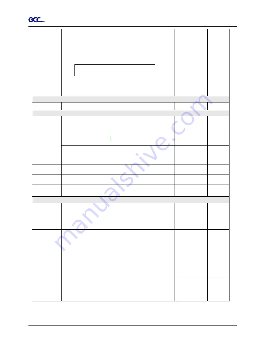
Copy: 
to copy the last job without re-sending the data. 
 
* 1mm gap will be auto-generated between 2 copies). 

* if the media length is not enough to continue, it will show 

below message on LCM:. 

O

p

O

t

u

S

f

a

;

c e

#

i

C

f

o

p

o

e

i

s

f

n

h

i s

e d


* if both functions are enabled at the same time, the cutter 

will 

 perform the last setting only.    

1~99; 
1 per step 


[ DATA CLEAR ] 


to clear up data memory. 


[ TOOL SELECT ] 

 Save 
 Parameter 

to save plotting parameters for later use.   

Patterns1~4 

Pattern 1 

Accept setup command: 
to accept commands of the Force, Speed, and Cutting 
Quality only via software. 


 Panel Setup 

Control panel only: 
to accept commands of the Force, Speed, and Cutting 
Quality only via control panel of the plotter.   


 Smoothing   
 Plot 

to enable smooth-cutting function. 


Enable 

 Set Pen’s   
 Lifespan 

To customize the length of Pen’s lifespan.   

  Unit: M 


 Restore    
 default 

to turn all parameters of the menu items to factory-default 
settings.  


[ MISC ] 

 Media Back  
 & Forth 

to enable to save time on repeated plotting jobs and better 
tracking.  
 
After plotting job has finished, the media will move back to 
the origin, then move to the end of the plot. 


 Disable 

 Set   
 

Communication


to build up the communication between host computer and 
plotter.  
 

Baud Rate

is to determine the speed of data transmission. 

Data Bits

 refers to the size of one block of data. 

Parity

 is used to check if data was revived correctly or not.


  9600, n, 8, 1, p 

9600pbs, 8 Bits with NO Parity 

19200, n, 8, 1, p 

19200pbs, 8 Bits with NO Parity 


 Firmware   
 Version 

to display the version number of Firmware and FPGA       
code. 


  Select Units    Provides two unit systems for users convenient. 

cm/gram;   
inch/oz 

Metric 

Содержание Vogue TP-183P

Страница 1: ...Apparel plotter TP 183P User Manual Great Computer Corporation...

Страница 2: ...information contained in this user manual at any time without prior notice un authorised modification copying distribution or display is prohibited All comments queries or suggestions concerning this...

Страница 3: ...2 3 3 Menu in off line mode 3 3 3 4 Description of menu items 3 4 4 Operation 4 1 Paper Loading 4 1 4 2 Adjusting the plotter 4 3 4 3 Tracking performance 4 4 4 4 Adjusting the plotting force 4 5 5 Ma...

Страница 4: ...1 piece of Stand Beam 2 pieces of Paper Take up and Feed shafts 2 pieces of Dancer Bars 2 pieces of Paper Hubs 2 white colored 2 pieces of Paper Hubs 3 black colored 4 pieces of Stand Holding Plug 1...

Страница 5: ...rollers Plotting Pad to protect the pen in the process of plotting consists of 14 control keys 1 LED and 1 LCM to show messages and menus Drum Tool Carriage to perform plotting with the installed pen...

Страница 6: ...ough a parallel interface cable Serial Interface Connector RS232C to connect the plotter and a computer through a serial interface cable USB Connector to connect the plotter and a computer through an...

Страница 7: ...n 25 and 75 in the workshop z Protect the machine from dust and strong air current z Prevent the machine from direct sunlight or extremely bright lighting Connect the Power Supply Carefully z Check th...

Страница 8: ...r Take Up System 2 1 Stand Components Component Quantity Description 2 Side Stand Roll holder support 2 Control board 1 for Paper Take Up System Dancer guiders 4 1 Stand Beam 2 Paper Take Up Feed Shaf...

Страница 9: ...of side stand and Stand Base by supplied screws A H 2 Fasten with Stand Beam by supplied screws B Figure 2 3 Figure 2 2 A H B A H 2 3 Plotter Setup Proceed as following Step 1 Place the plotter onto...

Страница 10: ...he wire goes through the hole showing in Figure 2 5 to reach power board Step 4 Plug in the head to the power connector see the details in Figure 2 5 2 6 2 7 and 2 8 Figure 2 5 Figure 2 6 The Wire goe...

Страница 11: ...r part Penholder Upper part Cap Refill of ink pen Spring Figure 2 11 Figure 2 10 Step 1 Take off the cap Hint put on the cap after jobs done to prolong the usage of the refill Step 2 Assemble the penh...

Страница 12: ...nnect the apparel plotter to a host computer and how to set up the computer apparel plotter interconnection Notice When USB connection is enabled both parallel port and serial port will be disabled au...

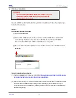
Страница 13: ...ill take a few minutes to find the device Please DO NOT disconnect the USB cable until the installation has completed 3 You can double click the USB icon on the taskbar to make sure the USB device is...

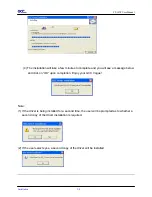
Страница 14: ...allation 2 7 Click Yes to continue NOTE If you use the Windows 7 Vista 64 bit program please note that a pop up window will be shown upon the initial installation as shown below 3 Click Next to start...

Страница 15: ...will see a message below and click on OK upon completion Enjoy your GCC Vogue Note 1 If the driver is being installed for a second time the user will be prompted as to whether a second copy of the dri...

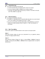
Страница 16: ...erial connector of your host computer at the assigned port COM1 or COM2 b Set up the communication parameters Baud Rate and Data Bits Parity to match the setting of your software package Refer to chap...

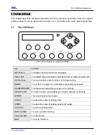
Страница 17: ...tions and error messages Power LED To indicate the power status light up power on light off power off 4 Arrow Keys To move position select function or change setting ENTER To set item or register the...

Страница 18: ...e T P 183P in processing U se to select E N T E R to enable the setting N on F unctional A t T his M odel C lear data m em ory N C ancel O K E N T E R 1S 72 F 80 O 0 275 M S elect O K E N T E R O ffse...

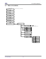
Страница 19: ...epeat Last Plot Select OK Enter Media Back Forth Select OK Enter Set Communication Select OK Enter Select Units Select OK Enter Scale Length Select OK Enter Scale Width Select OK Enter Smoothing Plot...

Страница 20: ...ume key again ONLINE OFFLINE 1 to switch between online mode and offline mode 2 to stop the plotting job or abort the change of setting Once press this key the plotting job will be terminated immediat...

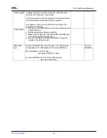
Страница 21: ...of the plotter Smoothing Plot to enable smooth cutting function Enable Set Pen s Lifespan To customize the length of Pen s lifespan Unit M Restore default to turn all parameters of the menu items to f...

Страница 22: ...as followng 1 Press the LEFT ARROW to choose the Numerator and select 500 0 mm 2 Plot the length by sending a graph file 3 Measure the length then use the RIGHT ARROW key to choose the Denominator the...

Страница 23: ...ll Paper Hub Feed Shaft paper roll and set it firmly Figure 4 1 Figure 4 1 Step 4 Install the shaft with Paper Roll onto the rear side of Roll Holder Support to to Figure 4 2 4 3 C1 E 1 C2 E 2 Step 5...

Страница 24: ...o dancer bars into the dancer guiders Figure 4 7 Detailed composition refer to Figure 2 1 Step 8 Adjust the two dancer bars to the position between sensors by loose or tighten the paper roll Figure 4...

Страница 25: ...lers from either the front side or the backside The color alignment rulers on the platen extension will help you to adjust the media precisely Step 3 Move the pinch rollers manually to proper position...

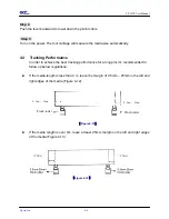
Страница 26: ...o achieve the best tracking performance for a long plot it s recommended to follow up below regulations If the media length is less than 4 m leave the margin of 0 5mm 25mm in the left and right edges...

Страница 27: ...the appropriate plotting conditions for the media are discovered After sizing the media press CUT TEST button to select the square cut and press ENTER KEY to confirm The default pen force of the cutti...

Страница 28: ...rails Use a vacuum cleaner to empty any accumulated dirt and media residue beneath the pinch roller housing Clean the platen and pinch rollers with a damp cloth or an alcohol immersed cloth then dry...

Страница 29: ...If need to remove the embedded or persistent dust use the lint free cloth or cotton swab moistened with rubbing alcohol 5 4 Cleaning the DU typed and A typed rollers on carriage Step 1 Turn off the a...

Страница 30: ...le brush toothbrush is acceptable to remove dust around the X axis and Y axis motors Figure 5 4 5 5 5 6 Cleaning the PC boards Step 1 Turn off the apparel plotter Step 2 Disassemble the front and rear...

Страница 31: ...n interface problem or a malfunction in your computer or a software problem Why is the apparel plotter not functioning Possible Causes 6 1 Non Operational Problems Check the following first Does the A...

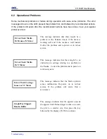
Страница 32: ...g well and if the media is well loaded Correct the problem and re power on to reboot system Error Check Media Or Y Motor This message indicates that there might be an obstruction to carriage relating...

Страница 33: ...o Chapter 4 Connecting your apparel plotter Yes No Refer to the MISC key in Chapter 3 Description of Operation for the port setup Try the communication between your apparel plotter and computer If it...

Страница 34: ...cable Yes No Most well known patterning software in the world has drivers for our apparel plotters If your software doesn t support TP 183P driver use software that has HP GL and HP GL 2 emulation su...

Страница 35: ...o Replace with a new pen Is tool force set up properly The default for tool force is 55 gf Yes No Is the tool offset set up properly Adjust the tool force to obtain an optimum pen force Refer to chapt...

Страница 36: ...Media Weight 40kg Acceptable Media g m 40g 80g Max Roll Media Diameter 200mm 7 87 Roll Media Core Diameter 50mm or 76mm 2 or 3 Hardware Interfaces USB Parallel RS 232 Data Buffer 4MB Commands HP GL HP...

Страница 37: ...ut Accessory Instruction A 2 1 Vogue CAD Output Accessory Instruction Chapter 1 Vogue CAD Output Accessory GCC plotter software Dongle Instruction 2 Chapter 2 The setting of GCC Plotter output 4 Chapt...

Страница 38: ...software please remove it from the control panel in your PC 2 Insert the installation CD and click setup exe 3 Click OK to continue with the installation 4 Click on the button shown below to install...

Страница 39: ...3P User Manual Vogue CAD Output Accessory Instruction A 2 3 7 Plug in the dongle and start the GCC plotter software You will see the window below showing that the installation has been completed corre...

Страница 40: ...he COM port 2 Please note that you must set the GCC plotter as the default printer 3 Click to set up the parameter as below and then click save The resolution should be set to 1016 lpi Note There are...

Страница 41: ...4 Click and choose to import the file PLT format you want to plot Note you can import the PLT file with different resolutions 5 Preview the file The length X and width Y of the image File name and pat...

Страница 42: ...anually to ensure that the coordinates are positive and thus will be outputted correctly 6 Click the icon to access the window below The following options are available 1 Click to modify the length an...

Страница 43: ...essory Instruction A 2 7 3 Click to indicate the starting segment of the textile marker or continue with the last plotting job 4 Click to output the file with a 1 1 ratio Enter the number of copies an...

Страница 44: ...n Pool and keep GCC plotter software in the online status 2 Copy the PLT file to C GCC Spool Assuming that the GCC plotter software has been installed in C The files in the spool will be output automa...

Отзывы: