background image

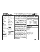
Wir gewähren auf dieses Erzeugnis eine Garantie von 

This product is warrantied for

Sur ce produit nous accordons une garantie de

24

Monaten

months

mois

Garantieurkunde

Servicestellen / Service / Service après-vente

Graupner-Zentralservice

Graupner GmbH & Co. KG
Postfach 1242
D-73220 Kirchheim

Espana


FA - Sol S.A.
C. Avinyo 4
E 8240 Maneresa

 (+34) 93 87 34 23 4

Italia

GiMax
Via Manzoni, no. 8
I  25064 Gussago

 (+39) 3 0 25 22 73 2

Schweiz

Graupner Service
Postfach 92
CH 8423 Embrach-Embraport

 (+41) 43 26 66 58 3

UK

GLIDERS
Brunel Drive
Newark, Nottinghamshire
NG24 2EG

 (+44) 16  36 61 05 39

Belgie/Nederland

Jan van Mouwerik
Slot de Houvelaan 30
NL 3155 Maasland VT

 (+31)10 59 13 59 4

Servicehotline


 (+49)(01805) 472876

Montag - Freitag
930 -1130 und 1300 -1500 Uhr

France

Graupner France
Gérard Altmayer
86, rue ST. Antoine
F  57601 Forbach-Oeting

(+33) 3 87 85 62 12

Sverige

Baltechno Electronics
Box 5307
S 40227 Göteborg

 (+46) 31 70 73 00 0

Luxembourg

Kit Flammang
129, route d’Arlon
8009 Strassen

 (+35) 23 12 23 2

Ceská Republika/Slovenská 
Republika

RC Service Z. Hnizdil
Letecka 666/22
CZ-16100 Praha 6 - Ruzyne

 (+42) 2 33 31 30 95

Die Fa. Graupner GmbH & Co. KG, Henriettenstraße 94-

96, 73230 Kirchheim/Teck gewährt ab dem Kaufdatum 

auf dieses Produkt eine Garantie von 24 Monaten. Die 

Garantie gilt nur für die bereits beim Kauf des Produktes 

vorhandenen Material- oder Funktionsmängel. Schäden, 

die auf Abnützung, Überlastung, falsches Zubehör oder 

unsachgemäße Behandlung zurückzuführen sind, sind von 

der Garantie ausgeschlossen. Die gesetzlichen Rechte 

und Gewährleistunsansprüche des Verbrauchers werden 

durch diese Garantie nicht berührt. Bitte überprüfen Sie 

vor einer Reklamation oder Rücksendung das Produkt 

genau auf Mängel, da wir Ihnen bei Mängelfreiheit die 

entstandenen Unkosten in Rechnung stellen müssen.

Graupner GmbH & Co. KG, Henriettenstraße 94-96. 73230 

Kirchheim/Teck, Germany guarantees this product for a 

period of 24 months from date of purchase. The guarantee 

applies only to such material or operational defects witch 

are present at the time of purchase of the product. Damage 

due to wear, overloading, incompetent handling or the use 

of incorrect accessories is not covered by the guarantee. 

The user´s legal rights and claims under garantee are 

not affected by this guarantee. Please check the product 

carefully for defects before you are make a claim or send 

the item to us, since we are obliged to make a charge for 

our cost if the product is found to be free of faults.

La société Graupner GmbH & Co. KG, Henriettenstraße 

94-96, 73230 Kirchheim/Teck, Allemagne, accorde sur 

ce produit une garantie de 24 mois à partir de la date 

d´achat. La garantie prend effet uniquement sur les vices 

de fonction-nement et de matériel du produit acheté. Les 

dommages dûs à de l´usure, à de la surcharge, à de 

mauvais accessoires ou à d´une application inadaptée, 

sont exclus de la garantie.

Garantie-Urkunde

Warranty certificate / Certificate de garantie

mx-12


 

4722 

mx-12  35-MHz


 

4722.B  mx-12  35-MHz-B


 

4723 

mx-12  40-MHz


 

4723.41  mx-12  41-MHz

Übergabedatum:

Date of purchase/delivery:

Date de remise:

Name des Käufers:

Owner´s name:

Nom de I`achateur:
Straße, Wohnort:

Complete adress:

Domicie et rue:

Firmenstempel und Unterschrift 

des Einzelhändlers:

Stamp and signature of dealer:

Cachet de la firme et signature 

du detailant :

Cette garantie ne remet pas en cause les droits et 

prétentions légaux du consommateur. Avant toute récla-

mation et tout retour du prouit, veuillez s.v.p. cotrôler et 

noter exactement les défauts ou vices.

Warranty            

47

Содержание MX-12 - PROGRAMMATION

Страница 1: ......

Страница 2: ...14 Input mode and function 15 Program Function mode 16 System mode 17 List mode 18 Function mode AIRPLANE Dual Rates and Exponential 19 Servo Reversing 19 Sub Trim 20 Travel Adjust 20 Elevator to flap...

Страница 3: ...s at regular intervals for damage to cases and leads Do not re use any item which is damaged or has become wet even after you have dried it out thoroughly Use only those components and accessories whi...

Страница 4: ...transmitters and any interference and may respond The model could then carry out uncontrolled movements which could easily result in personal injury or damage to property The servos may run to their...

Страница 5: ...on the winding can draw many times its nominal current when stalled and the high current will wreck the speed controller Electrical ignition systems Ignition systems for internal combustion engines c...

Страница 6: ...verse memory data are automatically converted if you switch modes Convenient wing mixer programs DIFFERENTIAL FLAPERON aileron differential mixer ELEVON deltas aileron elevator mixer V TAIL V tail mod...

Страница 7: ...control system fully expanded Switchable PPM SPCM modulation 4 proportional functions with trims 2 switched functions Order No 4722 35 MHz band Order No 4722 B 35 MHz B Band Order No 4723 40 MHz band...

Страница 8: ...n automatic charger Observe the recommendations provided by the charger manufacturer and the battery manufactu rer at all times Carry out a series of test charges to ensure that the automatic charge t...

Страница 9: ...ck lenght use the 2mm Allen wrench supplied with your mx 12 transmitter to unlock the set screw Turn the wrench counterclockwise to loosen the screw Then turn the stick clockwise to shorten or coun te...

Страница 10: ...initial setting for the throttle stick is ratched type If you don t like this feeling please follow the following instruction to change it You will be required a posidrive screwdriver and a pair of t...

Страница 11: ...F posi tion The transmitter will not transmit any radio fre quency RF in this position 2 Plug the supplied DSC cord into the DSC port in the rear of the transmitter 3 The encoder section of the transm...

Страница 12: ...be mounted using rubber grom mets and brass eyelets to isolate them from vibrati on Do not over tighten the mounting screws this will negate the vibration absorption effect of the rubber grommets The...

Страница 13: ...tions and installations 13 RECEIVER BATTERY WARNING Do not cut or fold the antenna ANTENNA R700 RECEIVER GYRO SWITCH HARNESS THROTTLE SERVO AILERON SERVO ELEVATOR SERVO GEAR CHANNEL RUDDER SERVO PITCH...

Страница 14: ...r exit the function mode The Key displays in this case Up Key Down Key Select Key Increase Key Decrease Key Clear Key Battery alarm and display When the transmitter voltage drops below 9 0 volts DC th...

Страница 15: ...ess simultaneously To enter and exit the System mode press simultaneously then turn on the power switch Advanced Digital Trim A D T The mx 12 digital trims feature the Direct Access display function W...

Страница 16: ...e Functions will appear in the same order they are shown on this chart Accessing the Mode Function 1 Move the power switch to the ON position 2 Press the Down and Select keys simultaneously 3 Use eith...

Страница 17: ...tion is explained on the page listed next to the function name Functions will appear in the same order they are shown on this chart Accessing the System Mode 1 Press the Down and Select keys simultane...

Страница 18: ...the transmitter power switch to the ON position Press the Up und Select keys simultaneously To scroll the functions first press the Down and Select keys FUNCTION LIST 1 FUNCTION LIST 2 SYSTEM LIST 1...

Страница 19: ...er switchin the ON positi on 2 Access the Function mode by pressing the Down and Select keys simultaneously 3 Press either the Up or Down key until D R EXP appears in the upper left corner of the LCD...

Страница 20: ...3 Press either the Up or Down key until SUB TRIM appears in the upper middle portion of the LCD 4 Press the Select key until the desired channel appears 5 Press the or key to establish the desired amo...

Страница 21: ...nd Select keys simultaneously 3 Move the elevator stick in the direction you want to mix with flaps Note The position indicator will reflect this change by highlighting the up or down arrow 4 Press th...

Страница 22: ...feature is used to cut or stop the engine without changing the position of digital throttle trim Throttle cut operating position 32 128 Go to Flap System menu Go to Ail Rud Mix menu Change value Set f...

Страница 23: ...Trim Include variety This mix is used any time the mix requires the slave channels trim position to be varied when the master channels digital trim position is varied An example for this type of mix w...

Страница 24: ...int for the slave channel Point that the mix is activated Press the Clear key to reset the value back to 0 3 Press the Down and Select keys simultaneously to exit the Programmable Mix function With a...

Страница 25: ...Change D R Exp menu Go to Fail Safe menu Accessing the Servo Travel Screen 1 Place the transmitter power switch in the ON positi on 2 Access the Function mode To do so press the Down and Select keys...

Страница 26: ...EXP appears in the upper left corner of the LCD 4 Press the or key until the desired channel aileron elevator or rudder appears 5 Select the switch position for which you want to adjust the rate The...

Страница 27: ...ss the or key to establish the desired amount and direction of Sub Trim Caution Do not use excessive sub trim adjustments since it is possible to overrun your servo s maximum Sub Trim Remember that it...

Страница 28: ...ame procedure for the remaining chan nels 7 Access the TRAVEL ADJ function by pressing the Down key 8 Access the THROTTLE CUT function by pressing the Up key 9 Exit the CCPM SETUP screen by pressing t...

Страница 29: ...during an autorotation This is very useful for practicing autorotation landings The throttle hold switch can be programmed to one of the four toggle switches Throttle hold will always be On in the for...

Страница 30: ...tle trim lever position will affect the low point position as shown when in the Normal mode Throttle Curve Throttle Stick P HIGH P MID P LOW Throttle Trim Operating Range Hovering Throttle Operating R...

Страница 31: ...understand There are three independent types of pitch curves available Normal Stunt and Hold Each pitch curve contains five adjustable points LOW 1 MID 3 and HIGH Note The pitch curve for the Throttl...

Страница 32: ...er operates in the same manner as the Hovering Throttle lever It is only operable while the flight mode switch is in the NORMAL position and its function is to shift the middle portion of the curve up...

Страница 33: ...neously Setting Up Revolution Mixing non heading lock gyros only Set up the helicopter so that it will hover with the tail rotor trim entered Establish the helicopter into a stable hover then steadily...

Страница 34: ...top of the LCD with the word OFFSET in the center of the LCD The value to the right is the mixing Offset neutral point currently 0 2 A new value for the offset can be selected using the or keys This i...

Страница 35: ...ravel Screen Neutral 50 100 Go to D R Exp menu Go to Fail Safe menu Accessing the Servo Travel Screen 1 Place the transmitter power switch in the ON positi on 2 Access the Function mode To do so press...

Страница 36: ...simultane ously will exit the Model Selection function and establish the model displayed as the new current model 5 Press the Select key to select the timer function to clear the Total Timer Press th...

Страница 37: ...of the current model to another model within the same transmitter This is very useful when setting up one aircraft several different ways or when trying an alternative setup of your current model Mode...

Страница 38: ...rection of control To Trainer menu To Modulation menu Select stick mode direction of control Select stick mode direction of control Return to Normal mode This is the procedure for changing stick mode...

Страница 39: ...s a slave transmitter and the other Master transmitter has a Pilot Link program active By selecting Pilot Link Slave the transmitter is automati cally in the correct programming mode to work as a slav...

Страница 40: ...efault The gear channel operates from the left upper gear switch AILE D R The gear channel operates from the aileron dual rate switch ROCKER The gear channel operates from the right rocker switch and...

Страница 41: ...ome function will be unavailable when certain functions are active With Flaperon active Elevon will be unavailable With Elevon active both Flaperon and V Tail will be unavailable Finally with V Tail a...

Страница 42: ...d move the power switch to the ON position to access the System mode 2 Press either the Up or Down key until WING TYPE appears on the LCD 3 Press the Select key to select the Elevon functions 4 Press...

Страница 43: ...on use the Servo Reversing function to reverse the travel direction Note Each servo s direction is adjusted individually through the Servo Reversing function For more information refer to the Servo Re...

Страница 44: ...tting 1 Servo Normal Swashplate Indicator Go to Model Select menu Go to Switch Select menu Turn selected type on or off Return to Default mode The Swashplate options are 1 Servo Non CCPM standard mixi...

Страница 45: ...requencies 45 Approved operating frequencies available crystals frequency pennants Thi situation in your own country It is prohibited to operate a radio control system on any frequency and channel oth...

Страница 46: ...ons of the FTEG Article 3 of the R TTE Directive when used for its intended purpose Angewendete harmonisierte Normen Harmonised standards applied EN 60950 EN 301 489 1 3 EN 300 220 1 3 Gesundheit und...

Страница 47: ...ion oder R cksendung das Produkt genau auf M ngel da wir Ihnen bei M ngelfreiheit die entstandenen Unkosten in Rechnung stellen m ssen Graupner GmbH Co KG Henriettenstra e 94 96 73230 Kirchheim Teck G...

Страница 48: ......

Отзывы: