134
Programming examples – Fixed-wing models
Using fl ight phases
Within any model memory you can program up to four
different fl ight phases (stages of fl ight), each incorpo-
rating settings which can be entirely different to the
others.
Each of these fl ight phases can be called up by
means of a switch or a combination of switches. Flight
phases represent the simplest and most conveni-
ent method of switching between different model set-
tings in fl ight, as they can be programmed suit diver-
se stages of a typical fl ight, such as normal, thermal,
speed, distance, etc.. However, fl ight phase program-
ming can also be used as a straightforward means of
trying out slight modifi cations to the control system
while the model is in the air, such as different mixer
ratios. This makes it much quicker to fi nd the optimum
settings for a particular model.
And this is how it’s done ...
We assume that you have already programmed the
model in the transmitter’s model memory, set it up ca-
refully, test-fl own it and trimmed it accurately.
1st step
»Phase setting« (page 78)
P h a s e 1 N o r m a l
2 . 0 s
P h a s e 2 T h e r m a l
1 . 0 s
-
P h a s e 3 S p e e d
3 . 0 s
-
P h a s e 4
0 . 0 s
-
N a m e S w i t c h t i m e s t a t u s
S E L
S E L
V
t
The fi rst stage is to assign names to one or more
fl ight phases, which should describe the various sta-
ges of fl ight. The name is important insofar as it helps
you to differentiate between the individual phases, but
it has no signifi cance at all in terms of programming
the transmitter. The name is always shown in the
basic display, as well as in all the menus which are
variable separately for each fl ight phase.
Selecting the appropriate menu line, choosing a
name and setting the transition time are carried out
by the “usual” method, i.e. by turning and pressing the
rotary control.
Note:
The names you assign to the various phases are of
no signifi cance in programming terms – with the ex-
ception of Phase 1, which should always be assigned
the name “Normal”. As such it is always active even if
you disable the fl ight phases.
For general model fl ying three fl ight phases are gene-
rally quite suffi cient:
• «Thermal» for launch and “staying up”,
• «Normal» for normal conditions, and
• «Speed» for fl ying in “top gear”.
In the “Trans. time” column you can defi ne the period
over which the transition from one phase
into
(!) ano-
ther fl ight phase occurs; this provides a smooth tran-
sition between the different servo settings, and can
prevent a possibly damaging lurch when you make
the switch under unfavourable circumstances. An as-
terisk (
) in the “Status” column indicates the current-
ly active fl ight phase.
2nd step
A physical switch must be assigned so that you can
switch between the different fl ight phases. The ideal
unit for switching up to three fl ight phases is the diffe-
rential switch, Order No.
4160.22
, which should be in-
stalled towards the outside of the transmitter on eit-
her side.
One fl ight phase is then assigned to each of the two
switch end-points,
starting from the centre point
.
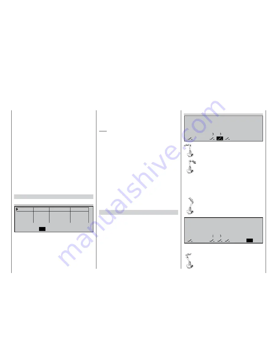
The phase switch is assigned in the menu ...
»Phase assignment« (page 80)
P H A S E A S S I G N M E N T
p r i o r
c o m b i
A
B
C
D
4 5
< 1 N o r m a l >
S E L
First select the switch symbol below “B”,
press the rotary control briefl y and move the
switch to one end-point, before returning it
to the centre position.
Now select the switch symbol below “C”,
give a brief press on the rotary control, and
move the switch to the
opposite
end-point.
The phase switch is now programmed cor-
rectly, but you still have to assign fl ight phases to
each switch position. Since you have already assi-
gned names to the fl ight phases, you will now see
the name of phase “1” on the right-hand side of the
screen.
Move the switch to the one end-point, and
select the
SEL
fi eld on the right of the
screen. Use the rotary control to select the
name you wish to assign to this fl ight phase
(in this example «2 Thermal»):
Repeat the procedure with the switch centre setting,
to which you assign the name «1 Normal».
Finally assign the name «Speed» to the
other end-point of the switch. A brief press
on the rotary control concludes the name
assignment process.
P H A S E A S S I G N M E N T
p r i o r
c o m b i
A
B
C
D
4 5
< 2 T h e r m a l >
S E L
Содержание MC-22S
Страница 1: ...1 mc 22s GB mc 22s 3D Rotary Programming System Programming manual ...
Страница 33: ...33 Digital trims ...
Страница 55: ...55 Program description Base setup model ...
Страница 77: ...77 Program description Flight phases ...
Страница 89: ...89 Program description Mixers ...
Страница 169: ...169 Approval certifi cates Conformity certifi cate EU conformity declaration Approval certificates Conformity Appendix ...
Страница 174: ...174 ...
Страница 175: ...175 ...
Страница 176: ...176 ...
Страница 177: ...177 ...
Страница 178: ...178 ...


