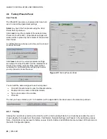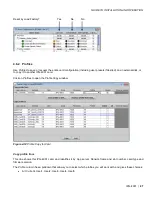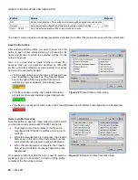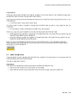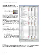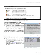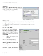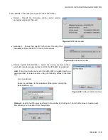
GUIDE TO INSTALLATION AND OPERATION
IPG-4901 |
19
•
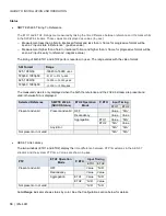
Link Offset
The Link Offset value is used when configuring the AES-67 in TR04 mode. See the Configuration section below
for details.
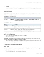
Configuration Controls
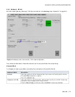
Two configuration control sections are provided. These are used, in conjunction with the Status data from the ETH1
and ETH2 status displays, to configure the SDI output timing, and to correctly integrate AES-67 audio into the SDI
outputs.
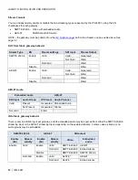
Separate Mode – SDI Output Config
Control
Function
+ 1 frame:
checkbox
Adds an extra frame to the startup buffer to deal with high-jitter streams; e.g.
from
server-based systems.
Separate Mode – AES-67
Control
Function
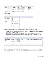
Link Offset:
Slider
Sets the time at which audio is output with respect to the PTP time.
Range: 0 to 100000
µ
sec (default is 0
µ
sec).
Adjustable in steps of 1
µ
sec or 1000
µ
sec.
Syntonize:
checkbox
Minimum Latency mode that over-rides the Link Offset control.
Packets are played out after a fixed number of packets.
This mode is a
debug aid
for commissioning purposes only.
Group Sync (TR-04) Mode
Use this mode for TR-04 operation.
•
Only the video controls are available; audio controls are disabled.
•
This mode requires PTP.
The IPG-4901
measures the timing of the delayed video using its RTP timestamps with respect to the system PTP
time. From this it calculates a link offset which is applied to the audio.
•
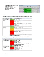
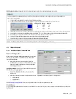
This applied link offset value is displayed in the Status area of the panel, beside the AES-67 link Latency status.
Video and audio are automatically aligned.
4.2.4 How to set up the timing on the IPG-4901
AES-67 Timing
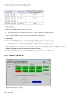
You can use the values presented in the ETH1 and ETH2 Link Latency displays, in conjunction with the following
information, to calculate the minimum value for the Link Offset.
•
The calculation depends on the selected audio profile
•
The IN RANGE status display simplifies the adjustment process.


