


Page 3
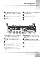
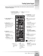
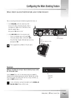
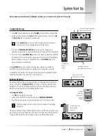
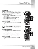
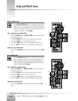
Take a look at the back of your Main Docking Station. The diagram below shows the various connections and configuration switches.
▼
▼
1
RS-485 IN and OUT JACKS -
4-position modular handset jacks used for RS-
485 communications between the camera system and other CameraMan
devices.
▼
▼
2
PVI COM JACK -
6-conductor RJ-11 jack used for communication with
Tracking Keypad in hard-wired mode.
▼
▼
3
IR TRANSMIT JACK -
Reserved for future use.
▼
▼
4
S-VIDEO OUT JACK -
Provides direct S-Video output through standard mini
DIN jack (cable is not provided).
▼
▼
5
COMPOSITE VIDEO OUT JACK -
Provides direct composite video output
through standard BNC-type jack (cable not provided).
▼
▼
6
ANTENNA -
RF receivers for the tracking power pack.
▼
▼
7
REMOTE DOCKING STATION PORT -
Reserved for future use.
▼
▼
8
RF CHANNEL SELECT -
Used to select which RF channel the Main Docking
Station will use to communicate with the Tracking Ring Package.
▼
▼
9
RS-232 PORT -
Standard DB-9 (female) connector provides RS-232
communications capability for devices like PCs or other vendor control
systems.
▼
▼
10
AUXILIARY COMMUNICATIONS PORT A -
Provides communications to
select CameraMan peripherals. Do not use unless otherwise specified.
▼
▼
11
AUXILIARY COMMUNICATIONS PORT B -
Provides communications to
select CameraMan peripherals. Do not use unless otherwise specified.
▼
▼
12
AUDIO: BALANCED JACK -
Standard XLR-type connector provides
balanced, audio output to connect to a standard mixer or similar audio
equipment.
▼
▼
13
AUDIO: UNBALANCED JACK -
Standard RCA-type connector provides
unbalanced, mono audio output to connect to a standard mixer or similar
audio equipment.
▼
▼
14
AUDIO: LEVEL SWITCH -
Used to configure the level of the audio
balanced (XLR) output- either LINE or MIC level, depending on the type of
audio system interfacing with the CameraMan system.
▼
▼
15
BASE UNIT PORT -
10 multi-conductor, 37-pin D-sub connector provides
communication between the Main Docking Station and the Camera
System.
▼
▼
16
DC POWER -
Power input for the Main Docking Station.
▼
▼
8
▼
▼
7
▼
▼
6
▼
▼
6
▼
▼
5
▼
▼
4
▼
▼
3
▼
▼
2
▼
▼
1
▼
▼
9
▼
▼
10
▼
▼
11
▼
▼
12
▼
▼
13
▼
▼
14
▼
▼
15
▼
▼
16
Содержание CameraMan 2018
Страница 1: ...CameraMan 2018 3012 Presenter Camera System Installation and Operation Manual L1206101 Rev B 1998 ...
Страница 3: ...CameraMan 2018 3012 Presenter Camera System ...
Страница 34: ...Page 31 ...
Страница 35: ......


