background image

Chapter 2 - Basic Operations

43

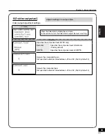
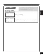
102 video output adj

Video output adjustment settings

LCD display

Press the Select dial to display the sub-menu.
In the sub-menu, turn the Select dial to adjust the level or setting.

Sub-menu

Specifi es the component level (NTSC only).

Betacam

Specifi es the component level to Betacam.
(Factory default)

SMPTE

Specifi es the component level to SMPTE.

Adjusts the composite/S gain.
Set specifi ed numerical value between -32 and 32. (Factory default: 0)

Adjusts the component gain.
Set specifi ed numerical value between -32 and 32. (Factory default: 0)

Adjusts settings on output video.

45

Содержание ADVC3000 -

Страница 1: ...User Manual 3000 ...

Страница 2: ...r this period the product will be in good working order Should our product fail to be in good working order Canopus will at its option repair or replace it at no additional charge provided that the product has not been subjected to misuse abuse or non Canopus authorized alternations modifications and or repair Proof of purchase is required to validate your warranty Canopus is not responsible for an...

Страница 3: ...can be generated on clothing and on people Before handling the product discharge static electricity from your body by touching a grounded metal surface Do not disassemble Do not remove the cover or modify the Product Fire electric shock or malfunction may result For internal inspection or repair please contact your system integrator or Canopus directly Do not operate at other than the specified vol...

Страница 4: ...fire or damage Also the unit may become deformed or change color Only setup using the prescribed method Do not setup in a manner other than prescribed Do not use while wrapped in cloth or plastic Heat can accumulate causing burns fire or damage If product will not be used for an extended period If this product will not be used for an extended period of time disconnect the power cord from the electri...

Страница 5: ...al may cause harmful interference to radio communications Operation of this equipment in a residential area is likely to cause harmful interference in which case the user will be required to correct the interference at his own expense CE Notice WARNING This is a class A product In a domestic environment this product may cause radio interference in which case the user may be required to take adequa...

Страница 6: ...uct 6 The analysis reverse engineering recompiling and disassembling of the software hardware or manuals that accompany this product and all other related products including miscellaneous supplemental items are prohibited 7 Canopus as written in both English and Japanese and its logo are registered trademarks of Canopus Co Ltd 8 ADVC is registered trademark of Canopus Co Ltd 9 Microsoft and Window...

Страница 7: ...7 3000 Table of Contents 9 ...

Страница 8: ...tration 11 1 5 Limitations 11 2 Features of ADVC3000 11 Chapter 2 Basic Operations 1 Part names and functions 14 1 1 ADVC3000 front panel 14 1 2 ADVC3000 rear panel 16 1 3 DIP switch settings 18 1 4 LCD screen displays 19 2 Connecting devices 26 2 1 Connecting ADVC3000 unit 26 2 2 Importing VCR data to your PC 28 2 3 Recording PC edited data onto a tape with VCR 29 3 Menu setting operations 30 3 1...

Страница 9: ...Introduction This chapter introduces topics you should know prior to setting up the ADVC3000 Before you using the ADVC3000 read this chapter to ensure a trouble free setup Introduction Features of ADVC3000 3000 11 ...

Страница 10: ...d 1 x Power cord clamp to prevent the power cord from accidentally pulling out 1 x DV cable 6 pin 4 pin 2 x Rack mount brackets 4 x Attachment screws 1 x ADVC3000 User Manual this document When mounting the ADVC3000 on a rack 1 Use a Phillips head screwdriver to remove the four rubber feet from the bottom of the unit 2 Attach the rack mount bracket to the ADVC3000 unit with the screws provided 12 ...

Страница 11: ...nc In this instance frame skip or frame hold will occur Limitations on the ADVC3000 connection Before you connect or disconnect your ADVC3000 to or from a PC ensure that the PC has been powered off Limitations on connecting your ADVC3000 to Windows 2000 PC through IEEE1394 interface OHCI When the ADVC3000 is operating in NTSC mode the DV frame rate being output from the OHCI driver is markedly slo...

Страница 12: ...4ch audio and can realize the conversion of the balanced audio embedded audio AES EBU and DV in any direction ADVC3000 also has a Sync Generator Black Burst output function thus it can be introduced to a variety of studio video systems v Easy to use input source switching With control buttons for switching the input source and peak meters on the easy to access front panel ADVC3000 enables easy set...

Страница 13: ...13 Chapter 2 Basic Operations This chapter explains the basics of the ADVC3000 such as part names functions etc Part names and functions Connecting devices Menu setting operations 3000 15 ...

Страница 14: ...he ADVC3000 unit on and off MENU button Switches between Main screen and Menu screen In sub menu press this button to return to the main menu STATUS LED Refer to page 15 for details Video input select button VIDEO IN Audio input select button AUDIO IN Chooses the video and audio input format Video input indicator Audio input indicator Displays the video and audio input format currently chosen Audi...

Страница 15: ... pin remote control is disabled Lit green 9 pin remote control is enabled Lit red 9 pin remote control has been set to enabled but remote control is prevented by a communication error Check that the 9 pin remote cable is correctly connected that the connected device s power is ON and that the remote control setting has been enabled on the connected device Flashing red A major ADVC3000 operation er...

Страница 16: ...l ANALOG AUDIO IN Unbalanced input Input connectors for unbalanced audio signal ANALOG AUDIO OUT Unbalanced output Output connectors for unbalanced audio signal MONITOR SDI IN OUT Input and output connectors for digial video and embedded audio signals When SDI input is detected the LED next to the SDI input connector lights red During SDI output the LED next to the SDI output connector lights red ...

Страница 17: ...nd then fix it with the provided power cord clamp refer to page10 DIP switch DV1 6 pin Use a DV cable to connect the ADVC3000 to a DV device or a PC Bus power is not supplied DV2 4 pin Use a DV cable to connect the ADVC3000 to a DV device or a PC REF OUT Output connector for reference signal sync signal Earth terminal Connect an earth wire to this terminal if necessary Refer to page 18 for details...

Страница 18: ...o Format Designates the video signal format Enabled only when the setting in the menu option 107 video standard is set by DIP switch OFF NTSC ON PAL SW4 PAL SECAM When SW3 is set to ON Enabled only when the setting in the menu option 107 video standard is set by DIP switch OFF PAL ON SECAM NTSC Setup Level When SW3 is set to OFF Enabled only when the setting in the menu option 107 video standard i...

Страница 19: ...he SDI ANALOG DV mode 1 Video Input Displays the video source 3 Audio Input Displays the audio status 5 Deck status Displays the status of the deck 4 Audio format Displays input channel and DV encode sampling frequency 2 Preset status Displays the preset status of video audio input Refer to page 33 for details Displays the remote control connector in use 8 9 pin remote control Displays the time co...

Страница 20: ...digital audio input connector is input BAL Signal from the balanced audio input connector is input UNBAL Signal from the unbalanced audio input connector is input SG 1kHz test audio is output 4 Audio format CH 1 4 32 k Converts the input audio signal CH1 to 4 to 32kHz 12bit 4ch audio CH 1 2 48 k Converts the input audio signal CH1 and 2 to 48kHz 16bit 2ch audio CH 3 4 48 k Converts the input audio...

Страница 21: ...run time code is used during built in color bar output or when time code is not input T_ is displayed if the time code set by 301 TC source cannot be found On the Main screen 2 Users bit UB 00 00 00 00 The letters or numbers designated by the user are displayed UB No DV signal is output U_ is displayed if the users bit cannot be found 7 Audio monitor status The channel is not monitored 8 9 pin rem...

Страница 22: ...onnector in use 7 9 pin remote control Displays the time code 5 On the Main screen 1 Input time code Displays the number designated by the user for identifying each tape 5 On the Main screen 2 Users bit 1 Video input DVCAM DVCAM signal is input DV DV signal is input SG Color bar is output No DV signal is detected 2 Preset status Displays the preset status of video audio input Refer to page 33 for ...

Страница 23: ...is shuttling Paused SHUTL Deck is shuttling EJECT No tape in deck 5 On the Main screen 1 Input time code TC 00 00 03 22 For PAL NTSC NDF Non Drop Frame A colon is used between seconds and frames as a delimiter TC 00 00 03 22 For NTSC DF Drop Frame A semicolon is used between seconds and frames as a delimiter TC No DV signal is detected Free run time code is used during built in color bar output or...

Страница 24: ...ode is enabled NOTES advanced setting is effective only when DV signal is output from the PC s IEEE1394 board 1394OHCI standard and _ is displayed 3 9 pin remote enabled disabled disable 9 pin remote control function is disabled enable A Remote control connector A is selected enable B Remote control connector B is selected 4 Time code select DVITC ADVC3000 is acquiring the time code from DVITC of ...

Страница 25: ... enabled and with 404 ext sync source set to input video REFin In SDI ANALOG DV mode Displayed when the REF signal cannot be detected in the REF IN connector sync cannot be locked with 109 Vout ref select set to REF In DV SDI ANALOG mode Displayed when the REF signal cannot be detected in the REF IN connector sync cannot be locked with 401 ext sync set to enable or advanced external sync is enable...

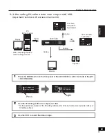
Страница 26: ...o a VCR with component connectors and a PC VCR with SDI input output Speaker Monitor Display PC S Video connector DV connector NOTES DV editing software is required to playback or capture video files for use on a PC or to record the file data onto tape In addition the PC should be equipped with an IEEE1394 connector CAUTION When connecting a PC to the ADVC3000 unit make sure that the PC s power is t...

Страница 27: ...page 26 and SDI connection shown above are possible at the same time Input source can be selected by the VIDEO IN button and the AUDIO IN button on the front panel NOTES DV editing software is required to playback or capture video files for use on a PC or to record the file data onto tape In addition the PC should be equipped with an IEEE1394 connector CAUTION When connecting a PC to the ADVC3000 un...

Страница 28: ...ONENT COMPOSITE S VIDEO SDI BALANCED AES EBU SDI ANALOG DV DV SDI ANALOG UNBALANCED ANALOG AUDIO INPUT LEVEL Engineered by Canopus Analog VCR with component input output Press the MODE button on the front panel of the ADVC3000 to switch the mode to SDI ANALOG DV 1 Capture the data by using DV editing software For the operational procedure of the DV editing software refer to the instruction manual ...

Страница 29: ... COMPOSITE S VIDEO SDI BALANCED AES EBU SDI ANALOG DV DV SDI ANALOG UNBALANCED ANALOG AUDIO INPUT LEVEL Engineered by Canopus Analog VCR with component input output Press the MODE button on the front panel of the ADVC3000 to switch the mode to the DV SDI ANALOG 1 Use the DV editing software to output your data For the operational procedure of the DV editing software refer to the instruction manual...

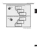
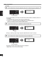
Страница 30: ...operations 3 1 Menu screen operations Press the Select dial or MENU button to go to the setting menu screen 1 Turn the Select dial to choose the menu item to set 2 5 0 8ă5 Turn Choose the menu item Setting menu is displayed on LCD 5 0 8ă5 Press 32 ...

Страница 31: ...Chapter 2 Basic Operations 31 Continued on the next page 33 Turn Turn Turn the Select dial counterclockwise to go back the setting menus Turn the Select dial clockwise to proceed to the setup menus ...

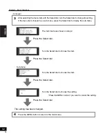
Страница 32: ...nu 3 Press the MENU button if you want to cancel the setting Press the MENU button to return to the main menu 4 Press the Select dial The item has been chosen in step 2 Press the Select dial Turn the Select dial to choose the item Press the Select dial Turn the Select dial to choose the item Press the Select dial Turn the Select dial to choose the setting Sub menu The setting has been changed Cont...

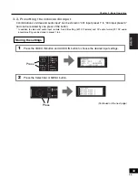
Страница 33: ...the button In addition to video and audio input remote A and B setting 501 9P remote and DV audio format 201 DV audio encode setting can be stored in preset 1 to 4 Storing the settings Press the VIDEO IN button and AUDIO IN button to choose the desired input settings 1 Press the Select dial or MENU button 2 Press 5 8 1 0 7 1 0 1 210 06 1 215 6 5 8 1 5 0 5 7 5 0 8ă5 Press Continued on the next page...

Страница 34: ...ted and press the Select dial to set the SKIP function Choose off when you want to cancel the SKIP function Confirm save current input is selected and press the Select dial 4 When you want to go back to step 3 press the Select dial when cancel is chosen Turn the Select dial to display save preset and press the Select dial 5 The setting is stored and the screen at the step 3 is displayed Repeat step...

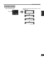
Страница 35: ...Recalling the settings Chapter 2 Basic Operations 35 Press the PRESET button Each time you press the button settings 1 to 4 are recalled in turn Press 5 8 1 0 24 5 6 1 210 06 1 215 6 37 ...

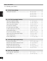
Страница 36: ...setting 106 Sout aspect info 47 Video standard settings 107 video standard 48 DV out frame synchronizer setting 108 DVout frame sync 48 Video output synchronizing signal settings 109 Vout ref select 49 Video out delay setting 110 Vout ref conf 49 Audio out delay setting 111 Vout audio delay 49 200 299 Audio input output settings DV audio encode setting 201 DV audio encode 50 Balanced audio headroo...

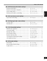
Страница 37: ...ttings Color bar output 601 SG output 56 SG audio level 602 SG audio level 56 700 799 Other detailed settings IEEE1394 clock adjustment 701 1394 clock adj 57 Local switch disable 702 local disable 57 Resample filter setting 704 resample filter 58 AV C transaction setting 705 AV C transaction 58 Maximum data rate setting 706 data rate cap 59 LCD backlight illuminating period settings 707 LCD backligh...

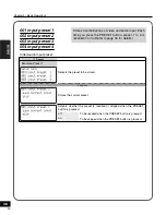
Страница 38: ...be stored Sub menu Stores the current preset Selects whether the preset is recalled or skipped when the PRESET button is pressed off To be recalled when the PRESET button is pressed on To be skipped when the PRESET button is pressed Stores 4 combinations of video and audio input Each time you press the PRESET button preset 1 to 4 is recalled in turn Refer to page 33 for details 40 ...

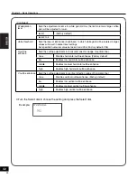
Страница 39: ...n and AUDIO IN button Sub menu items brightness Adjusts brightness of image The smaller the value is the darker the image is the larger the brighter Set specified numerical value between 0 and 1023 Factory default 512 contrast Adjusts contrast of image The smaller the value is the weaker the contrast is the larger the stronger Set specified numerical value between 0 and 255 Factory default 128 hue A...

Страница 40: ...8 component level Specifies the component level NTSC component only Betacam Sets Betacam Factory default SMPTE Sets SMPTE 3D visual processing Sets the effects for 3D noise reduction and 3D video processing NTSC only Available only to composite or S video none Disables the 3D noise reduction Factory default 3D Y C Enables 3D Y C composite only 3D NR low Enables low 3D noise reduction filter 3D NR mi...

Страница 41: ...nables high black gain filter B adaptation level Sets the adjustment volume for black expansion As the adjustment volume is larger the black gain becomes more emphasized level 1 Factory default level 2 to 4 black threshold Specifies the luminance level to enhance black element The higher the value the brighter the luminance level will be Set specified numerical value between 0 and 255 Factory default...

Страница 42: ...the outline adjustment for horizontal direction edge of vertical line none Disables horizontal outline enhance Factory default low Enables low horizontal outline enhance middle Enables medium horizontal outline enhance high Enables high horizontal outline enhance V outline enhance Sets the outline adjustment for vertical direction edge of horizontal line none Disables vertical outline enhance Fact...

Страница 43: ...level or setting Sub menu Specifies the component level NTSC only Betacam Specifies the component level to Betacam Factory default SMPTE Specifies the component level to SMPTE Adjusts the composite S gain Set specified numerical value between 32 and 32 Factory default 0 Adjusts the component gain Set specified numerical value between 32 and 32 Factory default 0 Adjusts settings on output video 45 ...

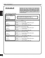
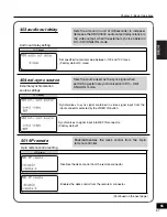
Страница 44: ...s not stop outputting video signal Factory default auto off Stops outputting video signal Specifies the composite output setting output Does not stop outputting video signal Factory default auto off Stops outputting video signal Specifies the S video output setting output Does not stop outputting video signal Factory default auto off Stops outputting video signal Specifies the output connector that a...

Страница 45: ...s the conditions where ADVC3000 automatically stops the DV stream in SDI ANALOG DV mode 104 DVout auto mute DV output auto off setting LCD display Does not stop DV stream Stops DV stream automatically when video is not input Factory default ...

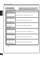
Страница 46: ...stream in16 9 aspect ratio squeeze For PAL SECAM Sets the DV stream in 4 3 aspect ratio Factory default Sets the DV stream in16 9 aspect ratio letter box Sets the DV stream in16 9 aspect ratio anamorphic This is effective only when the DV device to which the signals are output is compatible with the aspect signal of DV standard Specifies the aspect ratio for the DV stream that ADVC3000 outputs in S...

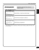
Страница 47: ... 4 3 aspect ratio Factory default Sets the S Video in16 9 aspect ratio letter box Sets the S Video in16 9 aspect ratio This is effective only when the video device to which the signals are output is compatible with the aspect signal of S Video standard Specifies the aspect ratio for the S Video that ADVC3000 outputs 49 ...

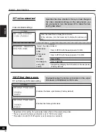
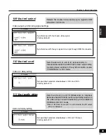
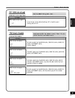
Страница 48: ...rear panel Factory default Specifies the video standard Once you have changed the video standard settings or the setup level you are prompted to turn the power off to make the new setting take effect 108 DVout frame sync DV out frame synchronizer setting LCD display Disables the frame synchronizer Factory default Enables the frame synchronizer Regardless of this setting the synchronizer takes effec...

Страница 49: ...tween 1024 and 1023 Factory default 0 Sets the amount in unit of 37 nanoseconds to increase decrease the ADVC3000 video output delay system phase relative to the synchronization source in SDI ANALOG DV mode 111 Vout audio delay Audio out delay setting LCD display Set specified numerical value between 100 and 100 msec Factory default 0 Sets the amount in unit of milliseconds to increase decrease the...

Страница 50: ...dB Sets to 20 dB Factory default for NTSC Specifies the output headroom 16 dB Sets to 16 dB 18 dB Sets to 18 dB Factory default for PAL SECAM 20 dB Sets to 20 dB Factory default for NTSC Specifies the input output headroom of the Balanced audio XLR 52 201 DV audio encode DV audio encode setting LCD display Encodes audio input CH1 and CH2 in the audio format of 48kHz 16bit Factory default Encodes aud...

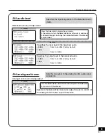
Страница 51: ...Sets to 4 dBm Factory default 0 dBm Sets to 0 dBm Specifies the output level of the balanced audio 4 dBm Sets to 4 dBm Factory default 0 dBm Sets to 0 dBm Specifies the input output level of the Balanced audio XLR 204 analog audio mon Analog monitor audio mixing output LCD display Turn the Select dial to select the channel and press the Select dial to turn on or off the channel Selected channels wil...

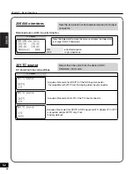
Страница 52: ...nnector Acquires time code from DVITC in SDI input and LTC Adopts LTC if LTC is acquired adopts DVITC only if not Factory default Reads the time code from the deck in SDI ANALOG DV mode 54 205 600 ohm term Balanced audio XLR input termination LCD display Press the Select dial to move the cursor and press the Select dial to change ON OFF alternately ON 600j termination OFF High impedance Sets the t...

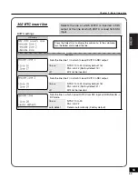
Страница 53: ...efault 16 PAL 6 to 22 Factory default 19 off Will not be inserted Sets the line line 2 in which to insert DVITC in SDI output line NTSC 10 to 20 Factory default 18 PAL 6 to 22 Factory default 21 off Will not be inserted Sets the line in which to read DVITC from SDI input in SDI ANALOG DV mode line NTSC 10 to 20 PAL 6 to 22 auto detect Detects automatically Factory default Selects the line at which...

Страница 54: ...External synchronization LCD display Disables the external sync operation Factory default Enables the external sync operation Enables the external sync operation as perfect sync mode The advanced setting is only available when DV signal is output from an IEEE1394 connector compliant with PC OHCI specifications For supported PC operating systems please refer to our website When the ADVC3000 is conne...

Страница 55: ...ANALOG mode 501 9P remote 9 pin remote control setting LCD display Disables the deck control from the remote connector Enables the deck control from the remote A connector Enables Disables the deck control from the 9 pin remote controller 57 403 audio out delay Audio out delay setting LCD display Set specified numerical value between 100 and 100 msec Factory default 0 msec Sets the amount in unit o...

Страница 56: ...on function cannot be used Free run time code is output Selects the color bar output mode 602 SG audio level SG audio level LCD display Sets to 18 dB FS Factory default for PAL SECAM Sets to 20 dB FS Factory default for NTSC Selects the testing audio signal of 1kHz in color bar output mode 58 Enables the deck control from the remote B connector Continued ...

Страница 57: ...O IN button and PRESET button Factory default Prohibits operation by the MODE button VIDEO IN button AUDIO IN button and PRESET button Prohibits operation by the MODE button VIDEO IN button AUDIO IN button and PRESET button only when the deck control by 9 pin remote connector is enabled Permits operation by the MODE button VIDEO IN button AUDIO IN button and PRESET button with the switching by AV ...

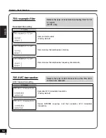
Страница 58: ...s that emphasizes frequency characteristic Selects the type of horizontal resampling filter for Cb Cr signal NTSC only 60 705 AV C transaction AV C transaction setting LCD display Executes AV C immediate transaction Factory default Sends INTERIM response and then executes AV C immediate transaction Selects the type of AV C transaction at the time AV C command is received ...

Страница 59: ...ay Sets to S100 Factory default Sets to S200 Sets to S400 Selects the maximum communication speed of the dr cap field of iMPR oMPR at the time of booting and setting change Once you have changed this setting you are prompted to turn the power off to make the new setting take effect 61 ...

Страница 60: ...ront panel Lights for 10 seconds after operating the front panel The backlight always lights Factory default Sets the backlight lighting period of the front panel LCD 708 LED dimmer LED brightness settings LCD display Turn the Select dial to display the sub menu In the sub menu turn the Select dial to select the brightness sub menu Sets to 50 brightness Sets to 100 brightness Factory default Power...

Страница 61: ...02 restore settings Restore settings Default settings Restores the current settings to the user setting or to the factory default Once you have changed this setting you may be prompted to turn the power off to make the new setting take effect 1 Turn the Select dial to select user 1 to 3 or factory default and press the Select dial user1 return the setting to user 1 setting user2 return the setting...

Страница 62: ...enu turn the Select dial to choose the sub menu item sub menu Displays uCOM version Displays FPGA version Displays CPLD 1 version Displays CPLD 2 version Displays unit ID The version numbers displayed above are examples and the actual screen may differ from the above screens This item contains sub menus displaying firmware version numbers ...

Страница 63: ...63 Chapter 3 Appendix 3000 This chapter provides supplementary information regarding the ADVC3000 operations Specifications 65 ...

Страница 64: ...Audio input SD SDI Embedded audio SMPTE 272M A AES EBU BNC x 2 CH1 to CH4 32 44 1 48kHz 16 20 24bit Unlocked Locked Can be converted anytime to 48kHz Locked by built in SRC Balanced XLR 3 31 x 4 CH1 to CH4 600j termination or high impedance is selectable Unbalanced Pin jack stereo 1 line CH1 and CH2 DV 32 44 1 48kHz Unlocked Locked 16bit 2ch 32kHz Unlocked Locked 12bit 4ch Audio output SD SDI Embe...

Страница 65: ...put level adjusting volume CH1 to CH4 Audio level meter Preset button Video input select button Video input indicator Audio input select button Audio input indicator Select dial Menu button Mode LED Status LED Other LCDs General specifications Power source AC 100 240V 50 60Hz Current consumption 0 44A 100V 0 21A 240V Operating temperature 10 35 C Outside dimension 430 W x 88 H x 270 D mm excluding ...

Отзывы: