background image

13

Grant Vortex Oil Boilers

4 - GENERAL BOILER INFORMATION

4.4.2 Fuel pipes

1

Fuel supply pipes should be of copper tubing with
an external diameter of at least 10 mm.
Galvanised pipe must not be used.
All pipe connections should preferably use flared
fittings. Soldered connections must not be used on
oil pipes.

2

Flexible pipes must not be used outside the boiler case.

3

A remote sensing fire valve must be installed in the
fuel supply line (outside) where it enters the building,
with the sensing head located above the burner.
Recommendations are given in BS 5410:1:1997.

4

A metal bowl type filter with a replaceable micronic
filter must be fitted in the fuel supply line adjacent to
the boiler. A shut-off valve should be fitted before the
filter, to allow the filter to be serviced.

5

A flexible fuel line, adaptor and 

1

/

4

" BSP isolation

valve are supplied loose with the boiler for the final
connection to the burner. If a two pipe system or
'Tiger Loop' type de-aerator is used, an additional
flexible fuel line (600 mm) and 

3

/

8

" to 

1

/

4

" BSP male

adaptor are available to purchase from Grant
Engineering (UK) Limited, Part No. RBS104.

6

Metal braided flexible pipes should be replaced
annually when the boiler is serviced. Long life
flexible pipes should be inspected annually and
replaced at least every 60 months.

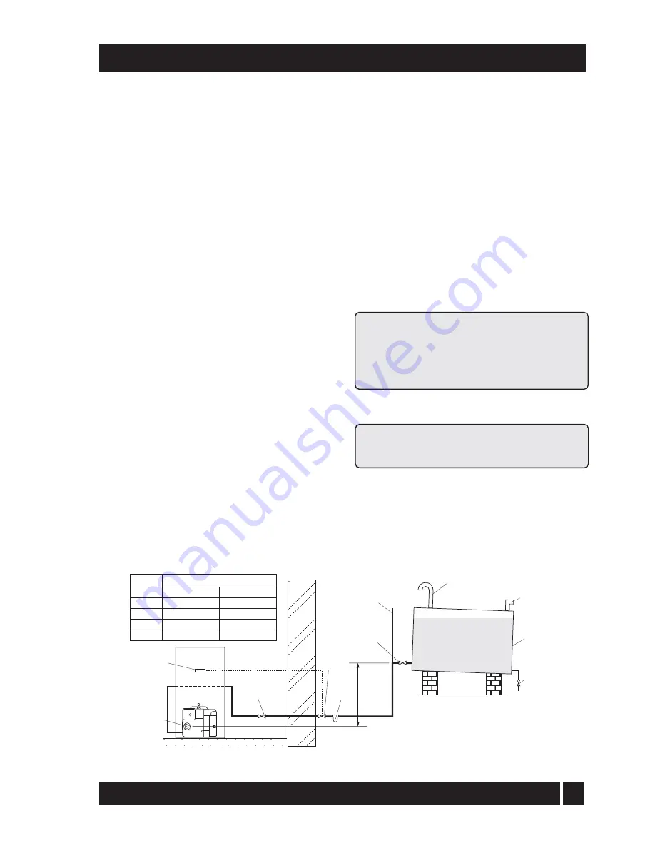
4.4.3 Single pipe system - (See Fig. 3)

1

Where the storage tank outlet is above the burner
the single pipe system should be used. The height
of the tank above the burner limits the length of
pipe run from the tank to the burner.

2

As supplied the burner is suitable for a single pipe
system.

4.4.4 Two pipe system  - (See Fig. 4)

1

When the storage tank outlet is below the burner,
the two pipe system should be used. The pipe runs
should be as shown in Fig. 4. The return pipe
should be at the same level in the tank as the
supply pipe, both being 75 to 100 mm above the
base of the tank. The pipe ends should be a
sufficient distance apart so as to prevent any
sediment disturbed by the return entering the
supply pipe.

2

Avoid the bottom of the tank being more than 3 m
below the burner.

3

A non-return valve should be fitted in the supply
pipe together with the filter and fire valve. A non-
return valve should be fitted in the return pipe if
the top of the tank is above the burner.

4

To be used with a two-pipe system, the burner
must be fitted with an additional flexible fuel line
(a flexible fuel line (600 mm) and 

3

/

8

" to 

1

/

4

" BSP

male adaptor are available to purchase from Grant
Engineering (UK) Limited), Part No. RBS104. See
Section 4.4.6.

5

The pump vacuum should not exceed 0.4 bar.
Beyond this limit gas is released from the oil.

For guidance on installation of top outlet fuel tanks and
suction oil supply sizing, see OFTEC booklet T1/139.
Available at www.oftec.org.uk.

Fig. 3 - Single pipe system

Filter

Fire
valve

Shut-off
valve

Shut-off
valve

A

Sludge
valve

Fill
pipe

Vent
pipe

Level
gauge

Fuel
storage
tank

Fire
valve
sensor

Pump

Head A

(m)

Maximum pipe run (m)

0.5
1.0
1.5
2.0

10mm OD pipe

10
20
40
60

12mm OD pipe

20
40
80

100

Содержание Vortex 15/26

Страница 1: ... No DOC 37 Rev 12 September 2006 Kitchen Kitchen System Utility and Utility System Models with outputs up to 70 kW Utility model Kitchen model This appliance is deemed a controlled service and specific regional statutory requirements may be applicable After installing the boiler leave these instructions with the User ...

Страница 2: ... 10 Fault finding 43 11 Burner spares 45 12 Health and safety information 47 13 EC declaration of conformity 48 Date Commissioningengineer Tel No Boiler model output kW Fuel type Kerosene Nozzle size Pump pressure Air setting Flue gas CO2 Net flue gas temp Smoke No It is recommended that the boiler should be regularly serviced at least once a year and the details entered in the Boiler Handbook by ...

Страница 3: ...that a temperature differential of 20 C between the flow and return is maintained The use of modulating circulating pumps now widely available and effective control systems should be considered The Grant Vortex boiler will however still operate at extremely high efficiencies even when it is not in condensing mode and therefore is suitable for fitting to an existing heating system without alteratio...

Страница 4: ... Kitchen model shown About your boiler 2 1 Boiler controls see Fig A 2 2 1 Ensure that There is sufficient fuel of the correct type in the supply tank and all fuel supply valves are open The water supply is on The electricity supply to the boiler is off The boiler On Off switch is set to OFF The room thermostat if fitted is at the desired setting The boiler thermostat is set to the required settin...

Страница 5: ...rmostat on your hot water cylinder this will control the temperature of your domestic hot water The boiler thermostat setting must be equal to or above the cylinder thermostat setting to enable the cylinder thermostat to control the domestic hot water system 2 Burner Lock out reset button If there is a burner malfunction a built in safety circuit switches the burner off and the Lock out reset butt...

Страница 6: ...aller or Service engineer to check the heating system for leaks and to check the expansion vessel air charge 2 USER INSTRUCTIONS The boiler or system will be fitted with an automatic air venttoremoveairfromthesystem Anyairtrappedinthe radiators should be removed by venting the radiators usingtheventscrewatthetopofeachradiator Onlyvent a radiator if the top is cool and the bottom is hot Excessive v...

Страница 7: ... diameter required for flexible flue liner Orange system For rigid flue system e g Green system 100 mm diameter flue required Refer to Sections 4 1 and 4 7 for further details Kitchen System Utility Utility System IMPORTANT On all models except 46 58 and 58 70 Return connections are stainless steel pipe see above for size Compression fitting MUST be used Brass push fit connectors are not suitable ...

Страница 8: ... 80 EH 0 75 80 EH 0 75 80 EH 0 85 80 EH 1 00 80 EH 1 00 80 EH 1 20 80 S 1 25 80 S 1 25 80 S 1 35 80 S 1 65 80 S 1 65 80 S 1 65 80 S 1 75 80 S Oil press bar 7 0 8 0 8 5 8 0 8 0 9 0 9 1 9 0 8 0 8 0 8 0 9 5 8 0 8 0 9 5 9 5 Smoke No 0 1 0 1 0 1 0 1 0 1 0 1 0 1 0 1 0 1 0 1 0 1 0 1 0 1 0 1 0 1 0 1 Fuel flow rate kg h 1 25 1 67 1 94 2 16 2 18 2 57 3 01 3 01 3 56 3 90 4 01 4 47 5 05 5 05 5 58 6 01 Flue ga...

Страница 9: ...re line RIGHT SIDE VIEW 631 59 PLAN VIEW 470 603 110 22mm condensate drain Safety valve Cold fill Flow 22mm push fit 22mm stainless return 170 Flue spigot 3 BOILER TECHNICAL INFORMATION Boiler dimensions 3 4 Fig 1a Kitchen and Kitchen System 15 26 dimensions Fig 1b Utility and Utility System 15 26 dimensions ...

Страница 10: ...SIDE VIEW 455 555 599 311 24 115 63 63 Flue centre line RIGHT SIDE VIEW PLAN VIEW 470 603 150 22mm condensate drain FRONT VIEW 470 900 28mm stainless return 205 Flue spigot 170 LEFT SIDE VIEW 731 831 1024 25 30 44 Dia 44 Dia 109 250 Flue centre line RIGHT SIDE VIEW PLAN VIEW 563 786 109 22mm condensate drain FRONT VIEW 563 1234 225 Flue spigot Note Cover plate on each side slides forwards to provi...

Страница 11: ...de of the door and boiler casing Adjust the bottom bracket until the door is correctly aligned Boiler components 4 2 The Grant Vortex range of automatic pressure jet oil boilers have been designed for use with a fully pumped central heating system with indirect domestic hot water cylinder They are not suitable for use with either a direct cylinder or a primatic cylinder or gravity hot water The bo...

Страница 12: ...S T200 A galvanised tank must not be used A plastic tank may be used and must comply with OFS T100 Note Plastic tanks should be adequately and uniformly supported on a smooth level surface across their entire base area Fuel supply 4 4 Installation of a Grant Vortex boiler must be in accordance with the following recommendations a Building Regulations for England and Wales and the Building Standard...

Страница 13: ...should be used The height of the tank above the burner limits the length of pipe run from the tank to the burner 2 As supplied the burner is suitable for a single pipe system 4 4 4 Two pipe system See Fig 4 1 When the storage tank outlet is below the burner the two pipe system should be used The pipe runs should be as shown in Fig 4 The return pipe should be at the same level in the tank as the su...

Страница 14: ...fuel fumes entering the building the de aerator must be fitted outside 3 To be used with a de aerator the burner must be fitted with an additional flexible fuel line a flexible fuel line 600 mm and 3 8 to 1 4 BSP male adaptor are available to purchase from Grant Engineering UK Limited Part No RBS104 See Section 4 4 6 Filter Fire valve Shut off valve Shut off valve Shut off valve See section 4 4 6 ...

Страница 15: ... line to the pump 6 Connect the 3 8 to 1 4 BSP adaptor to the flexible fuel line 7 Flexible fuel lines and adaptors are available to purchase from Grant Engineering UK Ltd 1 4 BSP female connections Tiger Loop SUPPLY TO PUMP RETURN FROM PUMP SUPPLY FROM TANK Fig 6 Tiger loop de aeration device 4 GENERAL BOILER INFORMATION Fig 7 Riello RDB pump 1 Oil inlet connection 2 Return connection 3 By pass s...

Страница 16: ...58 cm 56 in 715 cm 112 in Output Vent A Vent B 15 26 kW 116 cm 18 in 231 cm 36 in 26 36 kW 171 cm 27 in 341 cm 53 in Output Vent A Vent B 36 46 kW 226 cm 35 in 451 cm 70 in 46 58 kW 292 cm 45 in 583 cm 90 in 875 cm 136 in 58 70 kW 358 cm 56 in 715 cm 112 in 990 cm 154 in Output Vent C Vent D Vent E 15 26 kW 116 cm 18 in 231 cm 36 in 347 cm 54 in 26 36 kW 171 cm 27 in 341 cm 53 in 512 cm 80 in Outp...

Страница 17: ...ystem are available from Grant UK see Fig 10 1 The flue must terminate in a down draught free area i e at least 600 mm above the point of exit through the roof or preferably above the ridge level 2 The condensate may be allowed to run back into the boiler A condensate drain at the base of the flue system is not required 3 The flue terminal must be at least 600 mm from any opening into the building...

Страница 18: ...system is sealed and that condensate cannot escape Up to 1 5 l h of condensate can be produced in a conventional flue system Only use flue systems suitable for oil fired condensing boilers Do not use fire cement The use of high temperature silicone sealants is recommended 4 GENERAL BOILER INFORMATION Part No GFKIT 6 100 GFKIT 6 125 GFKIT 8 100 GFKIT 8 125 GFKIT 10 100 GFKIT 10 125 GFKIT 11 100 GFK...

Страница 19: ...e boiler flue outlet to the terminal is 8 metres for all Vortex boilers Balanced flue options 4 8 Extensions are available which extend the flue by 225 mm 450 mm or 950 mm An adjustable extension of 275 to 450 mm is also available A 45 elbow is also available No more than 2 x 45 elbows should be fitted per system Each elbow reduces the overall maximum length of the system by 1 metre 4 External bal...

Страница 20: ... models up to 26 kW output Starter kit standard Starter kit short 150 mm extension 250 mm extension 450 mm extension 950 mm extension 195 270 mm adjustable extension 45 elbow High level terminal Vertical terminal Wall bracket standard Wall bracket extended Part No GK90 GK90S GX150 90 GX250 90 GX450 90 GX950 90 GXA250 90 GE45 90 GTH90 GTV90 GWB90 GEB90 Vertical terminal kit GTV90 15 26 kW GTV200 26...

Страница 21: ...orner F From a terminal facing the terminal G From a surface facing the terminal H Vertical from terminals on the same wall I Horizontal from terminals on the same wall J Below an opening air brick window etc K From vertical sanitary pipework L Vertical flue from a wall M From an oil storage tank Min distance mm Terminal position 600 600 300 600 300 1200 600 1500 750 600 300 750 1800 Notes 1 An op...

Страница 22: ...ide for the return connection 22 mm for the 15 26 models or 28 mm for the 26 36 and 36 46 models The 46 58 and 58 70 models have a 1 BSP tapping on top of the boiler see Fig 12 A compression fitting must be used on the stainless steel return connection Holes are provided in the casing side panels to route the return to the left 15 26 models only see Fig 12a IMPORTANT All pipes to be fitted into th...

Страница 23: ...lines will invalidate the warranty Fig 12a View with rear panel removed 15 26 models only Sealed systems 4 13 See Fig 13 1 All Grant Vortex boilers are suitable for use with sealed systems complying with the requirements of BS 5449 The maximum temperature of the central heating water is 80 C 2 Thesystemmustbeprovidedwiththefollowingitems a Diaphragm expansion vessel complying with BS 4814 b Pressu...

Страница 24: ...itted The by pass must be an automatic type Fig 14 Sealed system boilers If thermostatic radiator valves are fitted the system must incorporate an adequate by pass 10 Filling of the system must be carried out in a manner approved by the local Water Undertaking Where allowed the system may be filled via the filling loop supplied the loop arrangement includes a double check valve assembly 11 All fit...

Страница 25: ...ge with an operating range of 1 to 4 bar c Pressure relief safety valve complying with BS 6759 and set to operate at 2 5 bar d Automatic air vent fitted to the flow pipe of the boiler ensures the boiler is vented e Filling loop This must be isolated and disconnected after filling the system 3 Refer to Section 3 2 for system volume and BS 7074 for further guidance Refer to Section 5 6 for further d...

Страница 26: ...rements Pipework Condensate disposal pipework must be plastic plastic waste pipe is suitable Copper or steel pipe is NOT suitable and should NOT be used The internal diameter of condensate disposal pipes should not be less than 20 mm e g 22 mm plastic plumbing pipe or 19 mm plastic overflow pipe Condensate disposal pipes must be fitted with a fall of 2 5 1 20 4 GENERAL BOILER INFORMATION For boile...

Страница 27: ...se made condensate soakaway 4 GENERAL BOILER INFORMATION IMPORTANT The trap MUST be checked at regular intervals e g on every annual service and cleaned as necessary to ensure that it is clear and able to operate It is recommended that if there is access to the left hand side of the boiler the condensate pipe be connected to the boiler using a tee piece and cap to form a rodding eye to allow clean...

Страница 28: ... boiler 5 1 Prepare the wall 5 2 5 BOILER INSTALLATION See Fig 19 and 19a If the boiler is to be used with a low level balanced flue Yellow system make the hole in the wall for the flue as shown in Fig 19a Note Dimension B given in Fig 19a includes an extra 10 mm over the size of the terminal to provide clearance for fitting Fig 19a Low level balanced flue Yellow System and Starter kit Green Syste...

Страница 29: ...r the size of the terminal to provide clearance for fitting Fitting instructions for the high level balanced flue and vertical balanced flue are supplied with the flue kits Adjustable sections The adjustable extensions are telescopic The wall terminal section is adjustable and is suitable for a wall thickness of 215 mm to 450 mm Simply adjust to the required length using a twisting motion The oute...

Страница 30: ... heating system Check all connections for leaks and rectify as necessary Make the water connections 5 4 5 BOILER INSTALLATION 1 Lift off upper rear casing panel 2 Remove the insulation from the underside of the panel do not discard it and remove the blanking panel Discard the blanking panel but retain the nuts and washers 3 Unscrew the protective covers from the studs on the flue dress panel suppl...

Страница 31: ... at 5 Amp must be taken to the boiler A three core cable is required to connect the boiler terminal block to the live supply Refer to Sections 9 5 and 9 6 for typical control system wiring diagrams 1 Lift off the boiler case top panel if it has not already been removed 2 Remove the top of the control panel Utility models or the wiring cover on Kitchen models and open the cable clamp Route the supp...

Страница 32: ...he boiler has been isolated before fitting the programmer Remove the screws holding the back of the control panel in place and move it back enough to allow access to the rear of the timer aperture 1 From underneath the control panel remove the screw securing the bracket behind the timer aperture Withdraw and discard the bracket 2 Remove the blanking piece from the timer aperture in the control pan...

Страница 33: ...en unscrew and remove the plug from the centre of the pump Using a suitable screwdriver rotate the exposed spindle about one turn Replace the plug and cap 5 BOILER INSTALLATION 6 Check the operation of the safety valve by turning the head anticlockwise until it clicks The click is the safety valve head lifting off its seat allowing water to escape from the system Check that this is actually happen...

Страница 34: ...screw on your vent manifoldtoventthesupplywhilethepumpisrunning 5 Set the boiler On Off switch to Off Check that all system controls are calling for heat and turn the boiler thermostat to maximum Switch on the electricity supply 6 Set the boiler On Off switch to On The burner fan should start and the burner should light within about 12 seconds If the burner does not light and the Lock out reset bu...

Страница 35: ... Switch off the boiler 19 With the system hot check again for leaks rectifying where necessary Drain the system while it is hot to complete the flushing process Refill and vent and pressurise if a sealed system the system 20 A suitable central heating system inhibitor must be added to protect the system against the effect of corrosion 21 Close the front door panel Kitchen models or replace the fro...

Страница 36: ...er is serviced and replaced every two years If in doubt replace the pipes Warning Before servicing set the boiler On Off switch to Off isolate the electricity supply and close the fuel supply valve Allow the boiler to cool The data label on the inside of the case side panel will indicate the fuel used and the nozzle fitted To ensure efficient operation of the boiler it is recommended that it is ch...

Страница 37: ...rfaces using a stiff brush and scraper if necessary 4 Check the condition of the flue clean as necessary 5 Check the condition of the front cleaning door seal replace if necessary 6 Replace the baffles ensuring they are correctly fitted See Fig 24 25 or 26 7 Pull out the spiral turbulators from the heat exchanger tubes See Fig 26 Clean the turbulators using a stiff brush Test the heat exchanger co...

Страница 38: ... the nozzle using a good fitting spanner 16 mm The use of an ill fitting spanner will damage the nozzle and could lead to an incorrect flame pattern Always check the electrode settings after replacing the nozzle see Fig 27 46 58 or 58 70 models See Section 11 2 and Fig 28 1 Combustion head Loosen the two screws securing the combustion head NOT the screws in the slotted ring Fig 30 and withdraw the...

Страница 39: ... tube until 0 lines up with the edge of the slotted ring Tighten the two screws All models 1 Photocell The photocell is a push fit in the burner body Carefully pull out the photocell to clean 2 Burner fan With the air intake grille or spigot removed remove the screws securing the fan housing cover R H side of burner and remove the cover Inspect the fan and housing and clean as necessary Replace th...

Страница 40: ...l Thermostat Limit Thermostat Heating ON Neon Green On Off Switch Chassis Earth To Main Casing N L CH OFF CH ON HW OFF HW ON Optional Grant Electronic 7 day Plug in Programmer 6 way Plug and Socket Connector L E N Burner Mains Supply Use 2 pole isolator with power ON indicator E N L G Y Bl Br G Y Bl Br R R R R R Br G Y G Y R R R Bl Bl Y R Bl Bl Br Br Bl Y Br R G Y G Y 4B 5B 1A 2A Blk Burner Lock o...

Страница 41: ...41 Grant Vortex Oil Boilers 9 WIRING DIAGRAMS Utility boiler control panel wiring diagram 9 3 Fig 33 Utility boiler Fig 34 Utility System boiler Utility System boiler control panel wiring diagram 9 4 ...

Страница 42: ... Plan HW CH controlled by two valves Typical control system wiring diagram Kitchen models 9 6 9 WIRING DIAGRAMS Fig 35 Utility models with Honeywell Y Plan HW controlled by mid position valve Typical control system wiring diagrams Utility and Utility System models 9 5 ...

Страница 43: ...filter Combustion air set Flame off and relights Boiler or flue blocked Combustion head set YES NO YES YES YES YES YES YES YES YES YES YES YES YES YES NO YES NO NO NO Check and set the electrodes Replace the control box Ignition spark proved NO NO NO NO NO OK NO NO NO NO Solenoid valve operating Replace control box Check oil pressure regulator Replace coil and or stem valve Nozzle atomising fuel N...

Страница 44: ...ondition of the fan Check room ventilation is adequate see Section 4 6 Check the nozzle size and type Fuel pressure may be too low check and adjust Insufficient draught clean boiler heat exchanger and check condition of flue Undersize nozzle and or low fuel pressure Check condition of boiler heat exchanger and clean if necessary Check the boiler thermostat Check the combustion settings Check the c...

Страница 45: ...6 46 3005788 RBS151 11 Photocell 3008646 RBS115 12 Capacitor 4 5 µF 3002837 RBS149 13 Seal kit 3008878 RBS140 Key No Description Riello Part No Grant Part No Key No Description Riello Part No Grant Part No 14 Needle valve 3007582 RBS109 15 Regulator 3008651 RBS120 16 Pump seal 3000439 RBS14 17 Pump 3008654 RBS101 18 O ring 3007162 RBS08 19 Filter O ring 3008653 RBS122 20 Connector 3003602 RBS35 21...

Страница 46: ...er 3008962 RBS168 13 Electrode 3020121 RBS158 14 Capacitor 5 µF 3008960 RBS167 15 Connector 3003602 RBS35 Key No Description Riello Part No Grant Part No Key No Description Riello Part No Grant Part No 16 Flexible pipe 3005720 RBS36 17 Motor 3008964 RBS159 18 Pressure gauge connector 3008876 RBS138 19 Tube 3008961 RBS160 20 Drive coupling 3000443 RBS16 21 Solenoid 3008648 RBS117 22 Solenoid lead 3...

Страница 47: ... Silicone elastomer Description Sealant and adhesive Known Hazards Irritation to eyes Precautions Avoid inhalation of vapour contact with eyes and prolonged or repeated contact with skin After handling always follow normal good hygiene practices Protection Use eye protection Rubber or plastic gloves should be worn where repeated contact occurs and a face mask worn when working in confined spaces F...

Страница 48: ...w voltage Electromagnetic compatibility and Boiler efficiency Directives 89 336 EEC 73 23 EEC 92 42 EEC This manual is accurate at the date of printing but will be superseded and should be disregarded if specifications and or appearances are changed in the interests of continued product improvement All goods sold are subject to our official Conditions of Sale a copy of which may be obtained on app...

Отзывы: