


As
6.
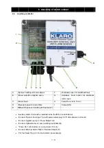
6.1 Co
A
P
B
C
C
M
D
A
6.2 As
sembly of
omponents
Piston Air Co
Control Unit K
Manifold with
Auxiliar Alarm
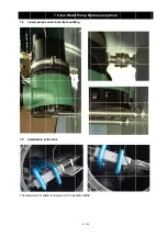
ssembly an
Find proper
o
Clos
o
Shad
A
B
C
D
f switch ca
ompressor
KL24plus
h Step Motor
m Unit
d installatio
location for t
se to the trea
dy as possib
6
.
Assem
abinet
Valves
on
the cabinet:
atment tanks.
ble
mbly of sw
13 / 25
E
F
G
. Mind given
witch cabin
Coolin
Powe
Remo
Alarm
length of air
net
ng Fan
er Supply
ote Alarm Pla
m LED (not fig
r hoses (5 me
E
F
G
ate
gured)
eter) and cab
E
bles