3-2
Spindl-Gard SG-1 and SG-2 Systems
L42110
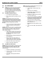
3.2.2
Initial Adjustments:
Proper filling and bleeding of the
system requires that the pneumatic and electric power
be supplied to the compo nents. The system needs to be
cycled to complete the bleeding operation, described in
paragraphs 3.2.3 through 3.2.5. Verify that the following
requirements exist:
For SG-1 systems, verify that a dedicated air
•
regulator supplies the spray nozzle and the
regulator is set at 15 psi (1 bar) on systems without
an air flow switch or 30 psi (2.1 bar) on systems
with an air flow switch.
NOTE
: If labyrinth or bronze seals are used on spindles with SG-1
systems, an additional air purge line may be required to maintain
2 psi internal head pressure. Contact a Graco representative for
recommended pressures.
For SG-2 systems, verify that a dedicated air
•
regulator supplies the mixing tee and the regulator
is set at 30 psi (2.1 bar) on systems without an air
flow switch or 60 psi (4.2 bar) on systems with an
air flow switch.
For pneumatic-operated systems, make sure air is
•
available to the supply pump and the pressure is
set according to pump specifications.
For all systems, check the controller to verify it is
•
set to the proper cycling times, usually 15 minute
intervals. Make sure power is present at the
controller and any zero-leak valves used in the
system. Manually operate the controller to verify
that proper signals are being sent and the desired
valves are energized.
Check setting of air flow switch (if used). Refer
•
to Sec tion 2 for air flow switch adjustment
procedures.
3.2.3
Bleeding Secondary Divider Valves
3.2.3.1
Procedures for bleeding secondary divider valves are the
same for both SG-1 and SG-2 systems. On many instal-
lations, a secondary divider valve is not used or is used
to supply lube points other than those relating to the
Spindl-Gard system. The first requirement in bleeding
secondary divider valves is to fill all supply lines from
the secondary divider valves to the lubrication point.
Refer to Figure 3-1 during the following procedures:
Loosen lube line at check valves located at
a.
each spray nozzle (Point A), mixing tee (Point
B) or bearing (Point C) which is supplied by the
secondary manifold.
Remove plug or performance indicator from the
b.
indicator port adjacent to each outlet tube of the
secondary manifold.
Install a lube fitting in the open indicator port and
c.
attach hand pump to the fitting.
Cycle hand pump until air-free lubricant is
d.
dispensed from the lube line (Point A, B or C).
Tighten lube line at Points A, B or C.
Remove hand pump and lube fittings at indicator
e.
ports of secondary divider valve and loosely install
plug. Do not tighten plug.
Repeat steps “a” through “e” at all indicator ports
f.
of the secondary divider valve.
3.2.3.2
When all supply lines have filled with oil per para graph
3.2.3.1, the secondary divider valve itself may be bled.
Refer to Figure 3-2 during the following procedure:
Remove indicator port plug or performance
a.
indicator from master divider valve outlet adjacent
to the out let supplying the secondary divider valve.
Install a lube fitting in the indicator port of master
b.
divider valve and attach hand pump to fitting.
Cycle hand pump until air-free lubricant is
c.
dispensed from loosened indicator port plugs on
the secondary divider valves.
Tighten all indicator port plugs or performance
d.
indicators at the indicator ports on the secondary
divider valves.
Repeat steps “a” through “d” at all indicator ports
e.
of the master divider valve. When complete, loosely
install plugs in indicator ports. Do not tighten plugs.
Refer to paragraph 3.2.4 or 3.2.5 to bleed master
f.
divider valves supplied by a pump or header
respec tively.
3.2.4
Bleeding Pump-Supplied Master Divider Valve
3.2.4.1
This procedure for bleeding a pump-supplied master
divider valve should be followed only after bleeding of
sec ondary valves and lube points have been completed
as dis cussed in paragraph 3.2.3. Figure 3-3 represents
a typical pump and master divider valve installation with
reference points relating to the procedure.
3.2.4.2
The procedure for bleeding pump-supplied master
divider valves is as follows:
Apply air and/or electrical requirements to pump.
a.
(Refer to paragraph 3.2.2.)
Fill reservoir and bleed pump.
b.
NOTE
: Plugs or indicators in indicator ports should be loose, as
per step “e”, paragraph 3.2.3.2.
Operate pump until master divider valve cycles
c.
several times and air-free oil appears at the
loosened indicator port plugs.
Tighten all plugs or performance indicators at
d.
indi cator ports of master divider valve.
Содержание SG2
Страница 1: ...Spindl Gard SG 1 SG 2 System Operation Service Instructions ...
Страница 2: ......
Страница 5: ...Spindl Gard SG 1 and SG 2 Systems 1 2 L42110 Figure 1 1 SG 1 System ...
Страница 8: ...1 5 Spindl Gard SG 1 and SG 2 Systems L42110 1 6 Blank Figure 1 2 SG 2 System ...
Страница 18: ...2 10 Spindl Gard SG 1 and SG 2 Systems L42110 Figure 2 10 Air Flow Switch and Mixing Tees ...
Страница 19: ......
Страница 26: ......
Страница 29: ...4 3 Spindl Gard SG 1 and SG 2 Systems L42110 4 4 Blank Figure 4 1 Spray Nozzle Figure 4 2 Mixing Tee ...
Страница 36: ......


