Operation
22
309457G
Operating Checklist
Check the following list daily, before starting to operate
the system, to help ensure you of safe, efficient opera-
tion.
Select a Fluid Nozzle and Air
Cap
The gun is supplied with Part No. 197266 Nozzle and
24A276 Air Cap. If you require a different size, refer to
Table 2 and Table 3 , and instruction manual 309419, or
consult with your Graco distributor. See Air Cap/Nozzle
Replacement on page 41.
A wide pattern kit (P/N 24A431) is included with the gun
and if installed, will provide more fan air for wider spray
patterns. (If pattern becomes split, use the fan air valve
to reduce the amount of fan air.)
* Also available in the following colors: 24A276 - blue,
24A277 - red, 24A278 - green
All operators are properly trained to safely
operate an automatic electrostatic water-
borne air spray system as instructed in this
manual.
All operators are trained in the Fluid Voltage
Discharge and Grounding Procedure on
page 21.
All operators are trained in the Pressure
Relief Procedure.
The warning sign provided with the gun is
mounted in the spray area where it can be
easily seen and read by all operators.
The system is thoroughly grounded and the
operator and all persons entering the spray
area are properly grounded. See Grounding
on page 18.
The condition of the gun’s electrical compo-
nents has been checked as instructed in Elec-
trical Tests on page 30.
All fluid hose connections are tight.
Ventilation fans are operating properly.
Workpiece hangers are clean and grounded.
All debris, including flammable fluids and rags,
is removed from the spray area.
All conductive objects in the spray area are
electrically grounded and the floor of the spray
area is electrically conductive and grounded.
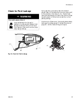
The manifold exhaust tubes have been
checked for the presence of any fluid as
instructed in Check for Fluid Leakage on
page 29.
WARNING
Pressurized Equipment Hazard
To reduce the risk of an injury, follow the
Pressure Relief Procedure on page 21
before removing or installing a fluid nozzle
and/or air cap.
Table 2: Fluid Nozzles
Part No.
Size,
mm (in.)
Part No.
Size,
mm (in.)
197263
0.75 (.030)
197266
1.5 (.055)
197264
1.0 (.042)
197267
1.8 (.070)
197265
1.2 (.047)
197268
2.0 (.080)
Table 3: Air Caps
Part No.
Pattern Shape
and Length in.
(mm)
Recommended Fluids and
Production Rates
24A438
Round end;
15-17 (381-432)
Light to medium viscosity.
Up to 15 oz/min (450 cc/min)
24A279
Round end;
14-16 (356-406)
Medium to high viscosity and
high solids.
Up to 15 oz/min (450 cc/min)
24A376*
Tapered end;
17-19 (432-483)
Light to medium viscosity.
Up to 15 oz/min (450 cc/min)
24A274
Tapered end;
12-14 (305-356)
Light to medium viscosity.
Up to 15 oz/min (450 cc/min)
24A439
Round end;
11-13 (279-330)
Medium to high viscosity and
high solids.
Up to 15 oz/min (450 cc/min)
For use with 2.0 mm nozzle.
Содержание PRO Auto Xs
Страница 51: ...Repair 309457G 51 ...


