background image

11 308-537

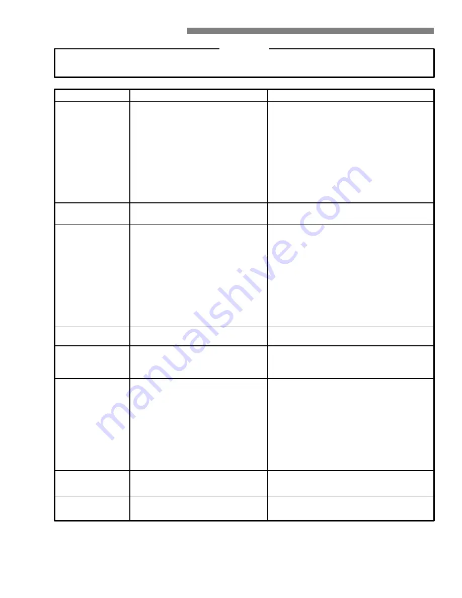
TROUBLESHOOTING CHART

WARNING

To reduce the risk of serious bodily injury, including fluid injection, splashing in the eyes or on the skin or injury

from moving parts, always follow the 

Pressure Relief Procedure Warning

 before proceeding.

PROBLEM

CAUSE

SOLUTION

Low pressure and/or

pump runs rough

Partially plugged air cleaner filter.
Spark plug dirty, wrong gap or wrong type.

Remove and clean.
Clean, adjust the gap or replace.
Replace with tip of proper size.
Clean. Check more frequently.
Check filter. Replace packings. See PUMP SERVICE.

Check water flow rate to pump.
Clean inlet and discharge valve assemblies. Check

filter.

Check garden hose, may be collapsed or kinked.
Replace worn valves.
Replace high pressure hose.

Worn or wrong size tip.
Inlet filter clogged.
Worn packings, abrasives in water or

natural wear.
Inadequate water supply.
Fouled or dirty inlet or discharge valves.

Even a small particle can cause the valve

to stick.
Restricted inlet.
Worn inlet or discharge valves.
Leaking high pressure hose.

Engine misses or

lacks power

Engine will not start or

is hard to start

Fill the tank with gasoline, open fuel shut off valve.

Check fuel line and carburetor.
Add to proper level.
Move switch to start position.
Drain fuel tank and carburetor. Use new fuel and dry

spark plug.
Open choke and crank engine several times to clear

out gas.
Remove and clean.
Clean, adjust the gap or replace.
Trigger spray gun.

No gasoline in fuel tank or carburetor.

Low oil
Start/Stop switch in Stop position.
Water in gasoline or old fuel.

Choked improperly. Flooded engine.

Dirty air cleaner filter.
Spark plug dirty, wrong gap or wrong type.
Spray gun closed.

Water leakage from

under pump manifold

Install new packings. See PUMP SERVICE.

Worn packings.

Water in pump

Humid air condensing inside crankcase.
Worn packings.
Oil seals leaking.

Change oil as specified in MAINTENANCE.
Install new packings. See PUMP SERVICE.
Install new oil seals. See PUMP SERVICE.

Frequent or premature

failure of the packings

Scored, damaged or worn plungers.
Abrasive material in the fluid being pumped.
Inlet water temperature too high.
Overpressurizing pump.

Excessive pressure due to partially plugged

or damaged tip.
Pump running too long without spraying.

Running pump dry.

Install new plungers. See PUMP SERVICE.
Install proper filtration on pump inlet plumbing.
Check water temperature; may not exceed 160

F.

Do not modify any factory–set adjustments. See

EQUIPMENT MISUSE HAZARD.
Clean or replace tip. See Installing and Changing

Spray Tips.
Never run pump more than 10 minutes without

spraying.
Do not run pump without water.

Strong surging at the

inlet and low pressure

on the discharge side

Foreign particles in the inlet or discharge

valve or worn inlet and/or discharge valves.

Clean or replace valves. See PUMP SERVICE.

Oil leakage between

the engine and the

pump

Worn oil seals and/or o-ring.

Replace oil seals and/or o-ring. See SERVICE

SECTION.

Содержание Hydra-Clean 1026

Страница 1: ...ies A 1000 psi 69 bar OPERATING PRESSURE 1400 psi 97 bar MAXIMUM WORKING PRESSURE HYDRA CLEAN 1530 4 HP ENGINE P N 800 717 Series A 1500 psi 103 bar OPERATING PRESSURE 1900 psi 131 bar MAXIMUM WORKING...

Страница 2: ...s injected directly into the bloodstream Consultation with a plastic surgeon or reconstructive hand surgeon may be advisable Pressure Relief Procedure To reduce the risk of serious bodily injury inclu...

Страница 3: ...ue to any kind of wear damage or misuse the high pressure spray emitted from it can cause a fluid injection injury or other serious bodily injury or property damage ALL FLUID HOSES MUST HA VE STRAIN R...

Страница 4: ...sure washer to prevent discharging high pressure fluid from the gun TERMS WARNING Alerts user to avoid or correct conditions that could cause bodily injury CAUTION Alerts user to avoid or correct cond...

Страница 5: ...E CONNECTION INLET WATER CONNECTION 3 4 GARDEN HOSE SPRAY GUN FOR THE 2340 ONLY FOR THE 1026 1530 Check for Shipping Damage Check the unit for any damage that may have occurred in shipping Notify the...

Страница 6: ...lation instructions Connect to Water Supply CAUTION Before attaching to the water supply check your local plumbing code regarding cross connection to the water supply A backflow preventer P N 801 133...

Страница 7: ...inue holding the rope as it returns Pull and return the rope until the engine starts In cool weather the choke may have to be kept closed for 10 to 30 seconds before opening it to keep the engine runn...

Страница 8: ...rigger safety latch on the gun is in the ON position before adjusting to avoid serious bodily injury or fluid injection Check the distance that you will need to hold the spray nozzle from the surface...

Страница 9: ...nd away from yourself and anyone else 3 Without holding your hand over the spray tip A pull back the quick coupler ring B Remove the old tip and or install a new one and then release the ring See Figu...

Страница 10: ...the pressure washer with a clean damp cloth 3 Perform the appropriate maintenance See maintenance chart MAINTENANCE Observing regular maintenance intervals helps ensure that you get maximum performan...

Страница 11: ...and clean Clean adjust the gap or replace Trigger spray gun No gasoline in fuel tank or carburetor Low oil Start Stop switch in Stop position Water in gasoline or old fuel Choked improperly Flooded en...

Страница 12: ...her 800 717 Hydra Clean 1530 Pressure Washer 17 14 13 24 12 9 11 4 10 2 3 6 7 3 7 19 27 3 2 23 30 31 28 29 22 21 20 1 8 25 43 44 46 45 25 23 22 20 1 2 3 21 5 18 35 36 37 38 39 40 41 34 33 32 42 50 51...

Страница 13: ...stems1 24 402 278 PLUG Plastic 1 25 802 781 KEY Square 3 16 x 1 1 2 1 26 803 966 TIP Spray 05 used on 800 682 only 1 804 322 TIP Spray 04 used on 800 717 only 1 REF PART NO NO DESCRIPTION QTY 27 804 3...

Страница 14: ...0 Pressure Washer 21 11 14 15 16 2 16 20 22 23 25 24 27 28 29 21 67 10 9 6 3 4 1 5 7 8 7 12 49 62 63 64 65 66 35 41 39 39 41 61 41 42 36 41 42 7 48 44 46 47 58 59 57 56 40 16 20 31 37 30 32 54 19 33 3...

Страница 15: ...32 800 392 GUN WAND ASSEMBLY incl 16 31 40 56 57 58 1 33 800 661 CHASSIS 1 34 801 539 BUMPER 1 35 803 925 HANDLE 1 36 800 175 FRONT LEG ASSEMBLY incl 39 41 42 60 61 1 REF PART NO NO DESCRIPTION QTY 3...

Страница 16: ...9 40 41 42 43 44 45 46 47 48 49 50 51 47 52 53 54 55 47 56 57 58 50 49 59 60 61 64 65 63 62 66 86 83 82 84 85 80 81 87 88 67 68 69 91 70 90 89 23 29 26 27 33 34 35 3 2 4 23 22 21 24 25 19 18 17 16 15...

Страница 17: ...1 34 804 022 BEARING Ball 1 35 804 009 CRANKSHAFT 1 36 804 007 KNOB Adjustment unloader 1 37 804 023 NUT Hex 1 38 804 029 SCREW Adjusting 1 39 804 019 O RING 1 40 804 006 REGULATOR Pressure 1 41 804 0...

Страница 18: ...36 37 38 39 40 41 42 43 44 45 46 47 48 49 50 51 47 52 53 54 55 47 56 57 58 50 49 59 60 61 64 65 63 62 66 86 83 82 84 85 80 81 87 88 67 68 69 91 70 90 89 23 29 26 27 33 34 35 3 2 4 23 22 21 24 25 19 18...

Страница 19: ...804 000 SEAT Valve 1 83 KIT 94 O RING 84 804 005 BODY CHEMICAL INJECTOR 1 85 KIT 94 O RING 86 KIT 94 BALL 87 KIT 94 SPRING 88 KIT 94 O RING 89 802 793 PLUG Hex Hd 1 90 801 484 PLUG Hex Hd 1 91 KIT 94...

Страница 20: ...RAWING 803 911 Pump Assembly 2300 psi 14 13 12 14 1 3 2 31 33 32 34 36 38 39 41 54 40 42 43 15 16 17 12 18 19 20 21 22 23 24 22 45 21 44 19 18 47 48 10 9 11 52 49 51 50 37 25 26 29 27 28 30 10 9 8 7 6...

Страница 21: ...30 802 793 PLUG Oil Drain 1 31 803 915 CRANKSHAFT 1 32 803 275 PIN Wrist 3 33 803 976 KEY 1 34 803 276 ROD Connecting 3 36 803 977 WASHER Lock 6 37 803 279 SCREW Cap socket hd 6 38 803 917 GUIDE Pist...

Страница 22: ...er or seals 3 Carefully examine each plunger for any scoring or cracking and replace as necessary Servicing the Plungers NOTE Plunger repair kit P N 801 474 is available to replace retainers o rings w...

Страница 23: ...th semi pneumatic wheels for portability BACKFLOW PREVENTOR 801 133 Prevent back up of contaminated water into fresh supply Install upstream of pump ANTI FREEZE FLUSH KIT 802 327 For flushing system w...

Страница 24: ...at a reasonable charge which charges may include the costs of parts labor and transportation DISCLAIMERS AND LIMITATIONS THE TERMS OF THIS W ARRANTY CONSTITUTE THE PURCHASER S SOLE AND EXCLUSIVE REMED...

Страница 25: ...odel 800 717 181 867 21 Label Replaced by 290 013 803 938 23 Label Replaced by 804 273 The following changes apply to the page 15 parts list for 800 654 Assembly No Series Letter Change Part That Chan...

Страница 26: ...654 800 129 51 Tip assembly 4005 Replaced by 805 552 801 640 65 Spray Tip 0005 Deleted 801 667 66 Spray Tip 1505 Deleted 801 614 63 Spray Tip 2505 Deleted 801 615 64 Spray Tip 4005 Deleted NEW Chemica...

Отзывы: