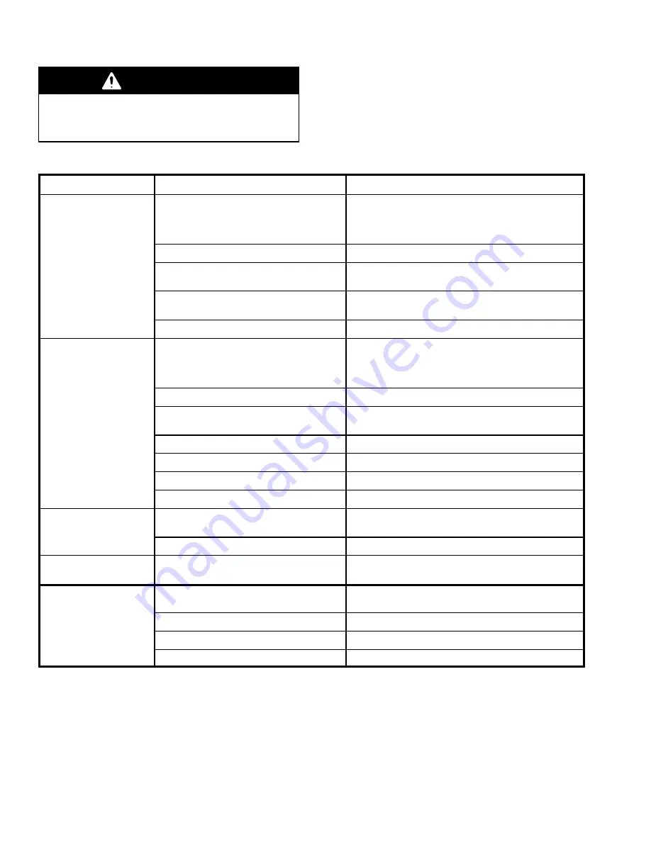
background image

12

309224

Troubleshooting

WARNING

To reduce the risk of serious injury whenever you
are instructed to relieve pressure, always follow the

Pressure Relief Procedure

 on page 10.

Before servicing this equipment, always make sure to

relieve the pressure.

NOTE:  

Check all possible problems and solutions

before disassembling the pump.

PROBLEM

CAUSE

SOLUTION

Pump fails to operate.

Inadequate air supply pressure or restricted
air line.

Increase air supply (see Technical Data on page
NO TAG).
See Maximum Working Pressure warning on page 8.
Clear line.

Closed or clogged air valves.

Open valves; clean.

Obstructed fluid hose or gun/valve;
fluid hose ID is too small.

Open, clear.* Use hose with larger ID, or use shorter
hose.

Dirty, worn, or damaged air motor parts.

Clean or repair; see pages 20 to 25. Lubricate with
grease.

Obstructed priming tube.

Open, clear.

Pump operates, but out-
put low on both strokes.

Inadequate air supply pressure or restricted
air line.

Increase air supply (see Technical Data on page
NO TAG).
See Maximum Working Pressure Warning on page 8.
Clear line.

Closed or clogged air valves.

Open valves; clean.

Obstructed fluid hose or gun/valve;
fluid hose ID is too small.

Open, clear.* Use hose with larger ID, or use shorter
hose.

Exhausted fluid supply.

Refill and reprime or flush.

Air leaking into supply container.

Check follow plate or inductor plate seal.

Fluid too heavy for pump priming.

Use inductor or follow plate.

Worn seals in displacement pump.

Replace seals. See page 18.

Pump operates, but out-
put low on downstroke.

Fluid too heavy for pump priming.

Use inductor or follow plate.

Held open or worn intake valve or seal (105).

Clear valve; replace seal.  See page 18.

Pump operates, but out-
put low on upstroke.

Held open or worn piston valve or seal (103).

Clear valve; replace seal.  See page 18.

Erratic or accelerated
pump speed.

Exhausted fluid supply.

Refill and reprime or flush.

Fluid too heavy for pump priming.

Use inductor or follow plate.

Held open or worn piston valve or seal (103).

Clear valve; replace seal.  See page 18.

Held open or worn intake valve or seal (105).

Clear valve; replace seal.  See page 18.

Relieve the pressure, 

and disconnect the fluid hose. Turn on the air. If the pump starts when the air is turned on, the clog is in 

  the fluid hose or dispense valve.

Содержание Falcon 244044

Страница 1: ...For lubricating products only 7500 psi 52 MPa 517 bar Maximum Fluid Working Pressure 150 psi 1 0 MPa 10 bar Maximum Air Input Pressure Model 244044 Series A 35 lb 16 kg Pail Size Model 244045 Series A...

Страница 2: ...ts and accessories D Check equipment daily Repair or replace worn or damaged parts immediately D Do not exceed the maximum working pressure stated on the equipment or in the Technical Data for your eq...

Страница 3: ...ays have the tip guard and the trigger guard on the gun valve when dispensing D Be sure the valve trigger safety operates before dispensing D Lock the valve trigger safety when you stop dispensing D F...

Страница 4: ...spensed D Keep the dispense area free of debris including solvent rags and gasoline D Do not smoke in the dispense area D Do not turn on or off any light switch in the dispense area while dispensing o...

Страница 5: ...at could cause damage to or destroy equip ment NOTE Identifies helpful procedures and information DISPENSE VALVE Any fluid dispensing device that can be triggered on and off Component Description This...

Страница 6: ...d screw back onto the pump and tighten securely Connect the other end of the wire to a true earth ground See Fig 2 Order part number 222011 Grounding Clamp and Wire D Fluid hoses Use only grounded flu...

Страница 7: ...to meet the system s requirements See the Maximum Working Pressure warning on page 8 Fig 3 KEY A Pump B Bleed type master air valve required Part No 110224 C Air regulator D Air hose E Air line quick...

Страница 8: ...rom the bottom of the container Mount the pump to the cover or other suitable mounting device WARNING Mount the pump securely so that it cannot move around during operation Failure to do so could resu...

Страница 9: ...filter F to remove harmful dirt and moisture from the compressed air supply 4 Install a second bleed type master air valve G upstream from all other accessories to isolate the accessories for servicin...

Страница 10: ...ispensing valve firmly to the side of a metal waste container and trigger the valve to relieve fluid pressure If you suspect that the spray tip or hose is completely clogged or that pressure has not b...

Страница 11: ...pressure and remove the hose Prime the pump alone then reconnect the hose and continue to prime your system 5 Use the air regulator to control the pump speed and the fluid pressure Always use the low...

Страница 12: ...arning on page 8 Clear line Closed or clogged air valves Open valves clean Obstructed fluid hose or gun valve fluid hose ID is too small Open clear Use hose with larger ID or use shorter hose Exhauste...

Страница 13: ...d actuator valve pin o rings 23 top or bottom Inspect and replace See page 21 Damaged actuator valve springs 16 top or bottom Replace See page 21 Worn or damaged carriage spool u cups 3c Characterized...

Страница 14: ...gures for sealant application instructions Required Tools The following tools are required to service the pump D Vise with soft jaws D Pipe wrench D Snap ring pliers D Needle nose pliers D Hammer D 3...

Страница 15: ...nch on the lower part of the outlet housing 18 to loosen the air motor 1 from the cylinder 101 See Fig 5 5 Continue to screw the motor 1 off the cylinder 101 by hand until the pin 112 joining the dis...

Страница 16: ...309224 Displacement Pump Service Fig 6 Fig 7 Rotate the cylinder 101 90 degrees so the hole is up Run a punch through the hole in the cylinder to drive the pin 112 out 101 18 8762C 101 112 8764C 17 1...

Страница 17: ...to secure the two rods 17 and 102 together Make sure the pin is flush or below the surface of the rod 17 Screw the motor 1 onto the cylinder 101 by hand See Fig 7 3 Use a pipe wrench on the lower par...

Страница 18: ...d without a pin hole and secure with the nut 109 Torque to 35 to 45 in lb 4 0 to 5 1 N m Lubricate the rod See Fig 9 2 Lubricate the o ring 111 and install it on the packing retainer 106 Slide the ret...

Страница 19: ...REF 102 107 REF 2 3 4 Torque to 15 to 20 ft lb 20 to 27 N m Lubricate Torque to 35 to 45 in lb 4 0 to 5 1 N m 5 Assemble pin 112 flush or below surface Flat side must face retainer 106 6 Large bevel m...

Страница 20: ...and the u cup packing 20 from the outlet housing 18 Reassembly 1 Lubricate the u cup packing 19 and install it in the bottom cylinder cap 4 with the lips facing up toward the air motor 1 See Fig 10 2...

Страница 21: ...o rings 34 and install them on the top cylinder cap 5 Install o rings 3g 23 and the pilot plug 68 Repeat for the bottom cylinder cap 4 See Fig 11 2 Install the top cap 5 on the cylinder 2 Be sure tha...

Страница 22: ...emove the top cap See Cylinder and Piston Service 5 Repeat for the bottom cylinder cap 4 Reassembly 1 If the o ring 24 was removed it must be installed from the inside of the top cap 5 Lubri cate the...

Страница 23: ...m Torque to 14 to 17 in lb 1 6 to 1 9 N m 5 Grease inner wall Long end of pin must point toward inside of motor Fig 11 3 8760D 11 15 16 23 12 34 A 2 22 5 25 34 25 12 23 15 16 11 18 4 22 17 27 30 14 3...

Страница 24: ...t 13 from the face of the cylinder 2 4 Clean and inspect all parts Replace any that are worn or damaged Reassembly 1 Install the valve gasket 13 and plate 8 on the cylinder 2 Be sure the surface of th...

Страница 25: ...be installed from inside of housing 3a 1 3 4 Lubricate with grease Torque to 14 to 17 in lb 1 6 to 1 9 N m 5 Grease inside diameter Fig 12 6 Lips point toward center of spool 25 7 28 8 13 2 1 2 2 2 2...

Страница 26: ...2 5 4 7 8 40 101 44 43 109 110 108 107 111 105 106 104 112 103 102 REF 102 112 17 REF 18 20 39 42 35 32 3g 14 22 22 11 11 15 15 16 16 23 23 12 12 19 36 13 25 26 25 34 34 28 25 17 29 27 27 107 REF 42...

Страница 27: ...0 71 in long 6 32 113755 O RING Buna N 1 34 156454 O RING Buna N 4 35 112840 NUT hex M8 x 1 25 1 36 113779 MUFFLER 1 37Y 196854 LABEL warning 1 39 150694 GASKET copper 1 40 116343 SCREW grounding 1 42...

Страница 28: ...inute Stroke length 3 25 in 82 5 mm Maximum pump operating temperature 130_F 54_C Air inlet size 3 8 npt f Fluid outlet size 1 4 npt f Wetted parts carbon steel zinc plating ductile iron polyurethane...

Страница 29: ...79 mm 9 88 in 251 mm 7 102 in 180 mm 14 lb 6 4 kg 244046 43 559 in 1106 mm 33 679 in 855 mm 9 88 in 251 mm 7 102 in 180 mm 16 lb 7 3 kg Port Sizes All Models E 3 8 npt f Air Inlet F 1 4 npt f Fluid Ou...

Страница 30: ...8 bar air pressure Test Fluid No 2 grease specific gravity 0 92 35 350 21 210 0 36 0 54 1 0 A B C D To find Fluid Outlet Pressure psi MPa bar at a specific delivery rate lb min or kg min and operating...

Страница 31: ...r air pressure Test Fluid No 2 grease specific gravity 0 92 0 560 0 336 0 36 0 54 1 0 A B C D 0 112 2 2 Cycles Per Minute 21 63 42 84 105 115 Recommended pump speed for continuous operation 95 cpm Max...

Страница 32: ...e available Any action for breach of warranty must be brought within two 2 years of the date of sale Graco makes no warranty and disclaims all implied warranties of merchantability and fitness for a p...

Отзывы: