


Form 140.940-IOM (DEC 2013)
INSTALLATION - OPERATION - MAINTENANCE
File:
SERVICE MANUAL - Section 140
Replaces:
140.940-IOM (FEB 2013)
Dist:
3, 3a, 3b, 3c
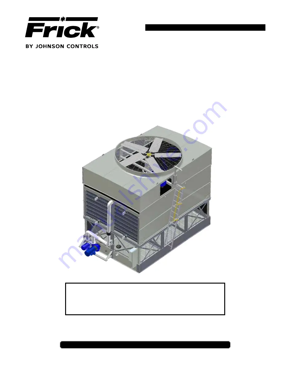
IDC2 Evaporative Condenser
THIS MANUAL CONTAINS RIGGING, ASSEMBLY, START-UP,
AND MAINTENANCE INSTRUCTIONS. READ THOROUGHLY
BEFORE BEGINNING INSTALLATION. FAILURE TO FOLLOW THESE
INSTRUCTIONS MAY RESULT IN PERSONAL INJURY OR DEATH,
DAMAGE TO THE UNIT, OR IMPROPER OPERATION.
Please check www.jci.com/frick for the latest version of this publication.


