background image

Installation 

4

308155U

Installation 

Grounding

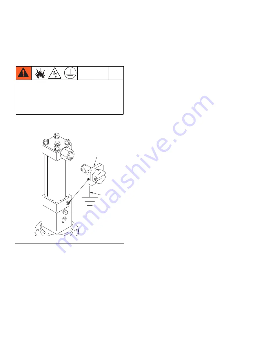
Pump: 

Use ground wire and clamp as shown in F

IG

. 1.

Hydraulic hose and fluid outlet hoses:

 use only elec-

trically conductive hoses 

Hydraulic power supply: 

Follow manufacturer’s rec-

ommendations.

Any pails used when flushing: 

Use only metal, 

grounded pails when flushing. Make firm metal-to-metal 
contact between the metal part of the dispense valve 
and the pail. Use the lowest possible pressure.

To ground the pump: 

Remove the ground screw (Z) 

and insert through the eye of the ring terminal at end of 
ground wire (Y). Fasten the ground screw back onto the 
pump and tighten securely. Connect the other end of the 
ground wire to a true earth ground. (F

IG

. 1)

The equipment must be grounded to reduce the risk 
of static sparking and electric shock. Electric or static 
sparking can cause fumes to ignite or explode. 
Improper grounding can cause electric shock.  
Grounding provides an escape wire for the electric 
current.

F

IG

. 1

Y

Z

Содержание Dyna-Star 224741

Страница 1: ...by Length 1500 psi 10 MPa 102 bar Maximum Hydraulic Input Pressure 1500 psi 10 MPa 102 bar Maximum Fluid Outlet Pres sure Model 224742 Series C 55 Gallon Length 1500 psi 10 MPa 102 bar Maximum Hydraulic Input Pressure 1500 psi 10 MPa 102 bar Maximum Fluid Outlet Pres sure Model 237653 Series B Stainless Steel Stubby Length Pump 1000 psi 7 MPa 70 bar Maximum Hydraulic Input Pressure 1000 psi 7 MPa ...

Страница 2: ... rags and spilled or open containers of solvent and gasoline Do not plug or unplug power cords or turn lights on or off when flammable fumes are present Ground all equipment in the work area Use only grounded hoses Stop operation immediately if static sparking occurs or you feel a shock Do not use equipment until you identify and correct the problem Keep a working fire extinguisher in the work are...

Страница 3: ...cables away from traffic areas sharp edges moving parts and hot surfaces Do not kink or over bend hoses or use hoses to pull equipment Keep children and animals away from work area Comply with all applicable safety regulations TOXIC FLUID OR FUMES HAZARD Toxic fluids or fumes can cause serious injury or death if splashed in the eyes or on skin inhaled or swallowed Read MSDSs to know the specific h...

Страница 4: ...spense valve and the pail Use the lowest possible pressure To ground the pump Remove the ground screw Z and insert through the eye of the ring terminal at end of ground wire Y Fasten the ground screw back onto the pump and tighten securely Connect the other end of the ground wire to a true earth ground FIG 1 The equipment must be grounded to reduce the risk of static sparking and electric shock El...

Страница 5: ...er 3 gpm 11 lpm S Hydraulic supply line T Check valve U Variable volume pressure compensated pump V Hydraulic power supply W Drain line accumulator X Low level cut off valve Y Thermal Relief Kit required Included in Hydraulic Fluid Control Kit 236864 which can be ordered separately Although the installation shown in FIG 2 is only a guide for selecting and installing system components and accesso r...

Страница 6: ...nto the system Carefully follow the manufacturer s recommendations on cleaning the reservoir and filter and periodically changing the hydraulic fluid Hydraulic Power Supply The hydraulic power supply system V must have a pressure reducing valve and a pressure compensated flow control A flow control valve R is required to limit the incoming flow to the reciprocator to a maximum of 3 gpm 11 lpm NOTE...

Страница 7: ...ly line R and mini mum 3 4 return line F on the reciprocator Contact your Graco representative for details of line sizing Pressure reducing valve N Circulates excess hydraulic fluid pressure back to the hydraulic power supply Install this valve N in the hydraulic supply line with a drain hose W teed into the hydraulic return line F Limit supply pressure to a maximum of 1500 psi 10 2 MPa 102 bar Ac...

Страница 8: ... return line shut off valve H and slowly open the hydraulic supply shut off valve L 3 Adjust the flow control valve R to limit the hydraulic flow to no more than 3 gpm 11 lpm which is approximately 60 cycles per minutes NOTE If Graco Part No 236864 hydraulic fluid control is used no adjustment is necessary 4 By adjusting the pressure reducing valve N adjust the hydraulic inlet pressure from 50 to ...

Страница 9: ...ighten the fit tings 1 5 58 which are self sealing and have replace able o rings If leaking persists change the o rings FIG 4 9 Model 237653 Tighten fittings B or K These fittings are self sealing and have replaceable o rings If leaking persists change the o rings FIG 5 FIG 4 self sealing fitting 1 5 58 o ring 1a 5a 58a reciprocator FIG 5 self sealing fitting B or K reciprocator o ring ...

Страница 10: ...Check and repair See page 11 Empty supply container Refill and reprime Do not allow pump to run dry Monitor closely or use a low level cutoff valve Pump runs but output low on up and or down stroke Pump piston and or intake valve worn Relieve pressure Check and repair See page 11 Pump runs but output low on both strokes Insufficient hydraulic fluid supply Check hydraulic supply Adjust to maximum 3...

Страница 11: ...cap 32 4 Remove the seals 16 44 and guide 19 from the top of the adapter 43 5 Lubricate the guide 19 and install the seals and guide in the adapter 43 one at a time in the order shown in FIG 6 6 Reassemble Torque the capscrews 46 to 28 to 32 ft lbs 38 to 43 N m Install the displacement pump Follow Step 24 page 17 NOTICE Keep the Hydraulic System Clean It is essential to keep the hydraulic oil syst...

Страница 12: ...screw it out of the pump adapter 43 and pull it off the pump 6 Pull the connecting rod 117 down as far as it will go Remove the cotter pin 118 from the bottom of the displacement rod assembly 34 and unscrew the connecting rod until it is free Model 237653 1 Flush the pump if possible and stop it with the dis placement rod in the lowest position 2 Relieve the pressure see Pressure Relief Proce dure...

Страница 13: ...rew 3 nuts 36 and lockwash ers 37 on top of the reciprocator FIG 8 3 Loosen both nuts on the fluid tube 45 Use a wrench to rotate the tube fittings 1 58 to the side and remove the tube 45 Check the o rings 1a 58a on the fittings and replace them if they are worn or damaged Install plugs in the fittings to pre vent contamination FIG 4 and FIG 5 NOTE See FIG 10 for Steps 4 to 12 except where noted 4...

Страница 14: ...ing screws to 96 to 100 in lbs 10 8 to 11 2 N m Remove excess sealant Allow 24 hours to cure before operating the reciprocator 10 Clean all sealant from the threads of any part you are reusing and apply thread sealant to the first two or three internal threads of the valve assembly 31 If you removed the capscrew 51 apply primer to its external threads let it dry for four minutes and torque the cap...

Страница 15: ...on page 11 Install the cylinder cap 32 FIG 13 18 If the tie rods 38 were removed reinstall them with the short threaded end up The other end should be screwed about 9 16 into the bottom cylinder cap 32 FIG 13 19 Install the o ring 49 in the deep lower groove of the piston 22 and install the seal 23 over the o ring Install the piston bearing 24 around the upper groove of the piston Holding the pist...

Страница 16: ...into the displacement rod 34 Install the cotter pin 118 make sure the o ring 119 in the bottom of the adapter 43 is in good condition Push the cylinder up into the adapter and engage the threads Screw in the pump using a strap wrench for the final tightening FIG 12 26 Connect the hydraulic supply and return hoses to the fittings 5 60 NOTICE Never install the fluid tubes 45 before you torque the ti...

Страница 17: ...lief Procedure page 8 2 Remove the intake valve Follow Disconnect the Reciprocator and Displacement Pump procedure on page 12 3 Carefully inspect the smooth inner surface of the cylinder 108 for scoring or irregular surfaces Such damage causes premature packing wear and leak ing replace the part as needed 4 Place the piston housing 104 in a vise Unscrew the piston seat 107 and remove the packings ...

Страница 18: ...9 and washer 23 7 Remove the packing nut 15 throat packings 9 19 and glands 6 8 from the outlet housing 16 8 Inspect all parts for damage Clean all parts and threads with a compatible solvent before reassem bling Inspect the polished surfaces of the displace ment rod 7 and cylinder 11 for scratches scoring or other damage which can cause premature pack ing wear and leaking To check run a finger ov...

Страница 19: ...the cylinder then reinstall the cylinder in the outlet housing 16 8 Install the ball 2 guide 22 o ring 12 and ball stop pin 5 in the intake valve housing 13 Place the intake valve assembly in the cylinder 11 Apply thread lubricant to the locking ring and cylinder 11 and screw the ring onto the cylinder 9 Reconnect the displacement pump to the reciproca tor by performing the reverse of the disassem...

Страница 20: ...Parts 20 308155U Parts 34a 34b 34c 49 38 46 52 33 Ref 46 43 44 19 16 32 18 20 21 20 22 13 9 26 29 31 37 36 24 23 4 51 25 17 5 59 40 label 45 58 7 6 1 14 5a 1a 58a 12 3 39 2 30 60 16 13 7 ...

Страница 21: ...55 RETAINER spring cs 2 21 178189 SPRING compression steel 1 22 192656 PISTON cs 1 23 178226 SEAL piston 1 24 178207 BEARING piston bronze filled PTFE 1 25 178229 CYLINDER motor cs 1 26 192654 STOP valve cs 1 29 192654 SLEEVE valve steel 1 30 178181 PLATE cap 1 31 239874 SPOOL VALVE ASSEMBLY 1 32 186225 CAP cylinder bottom cs 1 33 183833 BASE aluminum 1 34 222301 DISPLACEMENT ROD ASSEM BLY contact...

Страница 22: ...INDER displacement 1 109 101190 BALL steel 1 25 mm dia 1 110 183009 BODY valve 1 111 156633 O RING nitrile rubber 1 112 157182 RETAINER ball 1 113 171590 WASHER spreader 2 114 158402 PACKING leather cup 2 115 171594 WASHER back up 2 116 100279 STEEL ball 0 88 22 2 mm dia 1 117 183529 ROD connecting 1 118 100103 PIN cotter 0 125 3 2 mm dia 1 5 38 mm long 1 119 108993 O RING buna N 1 120 183741 LABE...

Страница 23: ...PISTON cs 1 23 178226 SEAL piston glass filled PTFE 1 24 178207 BEARING piston bronze filled PTFE 1 25 178229 CYLINDER motor cs 1 26 192654 STOP VALVE cs 1 29 189072 SLEEVE valve steel 1 30 178181 PLATE cap 1 32 178235 CAP cylinder bottom 1 33 178233 RETAINER housing 1 34 222301 DISPLACEMENT ROD ASSY includes 34a to 34c 34a 188078 ROD displacement 1 34b 105765 PACKING o ring 1 34C 178232 STOP disp...

Страница 24: ...6133 V PACKING throat female sst 2 10 176637 PIN ball stop piston sst 1 11 186994 CYLINDER sst 1 12 164846 O RING PTFE 1 13 186992 HOUSING valve intake sst 1 14 186993 STUD piston sst 1 15 186995 PACKING NUT WET CUP sst 1 16 205999 HOUSING outlet sst 1 17 164630 RING locking sst 1 19 170625 V PACKING throat UHMWPE 1 22 164679 GUIDER ball intake sst 1 23 176634 WASHER piston sst 1 24 186990 GLAND p...

Страница 25: ...Hydraulic Fluid Input Volume 6 gpm 11 7 lpm Fluid Consumption Rate 6 5 ounces per cycle or 1 gal lon per 19 5 cycles 0 195 liters per cycle or 1 gal lon per 19 5 cycles Maximum Fluid Temperature 130 F 55 C Pressure Reducing Valve Adjustment Range 50 to 1500 psi 0 34 to 10 MPa 3 4 to 102 Bar Effective Piston Area 1 48 in 2 9 55 cm 2 Piston Rod Diameter 1 375 in 34 9 mm Output Per Cycle 0 055 gpm wi...

Страница 26: ...ion is square with mounting holes 3 536 in 90 424 mm 8 62 in 219 mm Displacement Pump 23 37 in 594 mm Model 224741 34 3 in 871 mm Displacement Pump and Drop Tube 3 8 npt f hydraulic supply port Fluid Inle Stubby Pump 1 1 2 NPT for models 224741 224742 3 4 NPT for model 237653 t 14 75 in 375 mm Reciprocator Model 239882 and 217222 3 4 npt f hydraulic return port 1 2 npt f fluid outlet port 49 in 12...

Страница 27: ...Notes 308155U 27 Notes ...

Страница 28: ... of the equipment does not disclose any defect in material or workmanship repairs will be made at a reasonable charge which charges may include the costs of parts labor and transportation THIS WARRANTY IS EXCLUSIVE AND IS IN LIEU OF ANY OTHER WARRANTIES EXPRESS OR IMPLIED INCLUDING BUT NOT LIMITED TO WARRANTY OF MERCHANTABILITY OR WARRANTY OF FITNESS FOR A PARTICULAR PURPOSE Graco s sole obligatio...

Отзывы: