12
308357
Service
WARNING
To reduce the risk of serious injury whenever you
are instructed to relieve pressure, always follow the
Pressure Relief Procedure
on page 8.
REQUIRED TOOLS
D
Set of adjustable wrenches
D
15/16 in. (or 23 mm) socket wrench
D
Large pipe wrench
D
Torque wrench
D
Rubber mallet
D
O-ring pick
D
Large vise
D
Thread lubricant
D
Thread sealant
D
Loctite
R
2760
t
or equivalent
DISCONNECTING THE DISPLACEMENT
PUMP
1.
Flush the pump, if possible. Stop the pump at the
bottom of its stroke and
relieve the pressure
.
2.
Disconnect the air hose and fluid hose.
3.
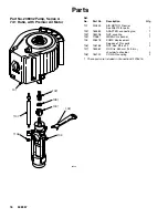
Disconnect the displacement pump (105) from the
motor (101) as follows. Be sure to note the relative
position of the pump’s fluid outlet (U) to the air inlet
(V) of the motor. If the motor does not require
servicing, leave it attached to its mounting.
CAUTION
Be sure to use at least two people when lifting,
moving, or disconnecting the pump. This pump is too
heavy for one person. If you are disconnecting the
displacement pump from a motor which is still
mounted (for example, on a wall bracket), be sure to
support the displacement pump while it is being
disconnected, to prevent it from falling and causing
injury or property damage. Do this by securely
bracing the pump, or by having at least two people
hold it while another disconnects is.
If the pump is mounted on a cart, slowly tip the cart
backward until the handle rests on the ground, then
disconnect the displacement pump.
4.
Using an adjustable wrench (or hammer and
punch), unscrew the coupling nut (103) from the
connecting rod adapter (102). Remove the cou-
pling collars (108). Take care not to lose or drop
them. See Fig. 4.
5.
Hold the tie rod flats with a wrench to keep the
rods from turning. Unscrew the nuts (106) from the
tie rods (107). Carefully remove the displacement
pump (105) from the motor (101).
6.
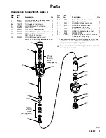
Refer to page 14 for displacement pump service.
To service the air motor, refer to the separate
motor manual, supplied.
RECONNECTING THE DISPLACEMENT
PUMP
1.
Ensure that the rod adapter (102) has not loos-
ened during maintenance. Proper torque is neces-
sary to prevent the rod adapter from loosening
during the pump operation.
If the rod adapter (102) has loosened, remove it
and apply Loctite
R
2760
t
(or equivalent) to the
rod adapter and air motor piston threads.
Screw the adapter (102) into the air motor shaft.
Hold the motor shaft flats with a wrench to keep it
from turning, and torque the adapter to 312–340
N.m (230–250 ft–lb). See Fig. 4.
2.
Screw the tie rods (107) into the base of the air
motor (101). Using a wrench on the tie rod flats,
torque to 129–142 N.m (95–105 ft–lb).
3.
Make sure the coupling nut (103) and the coupling
collars (108) are in place on the displacement rod
(1).
4.
Use at least two people to hold the displacement
pump while another reconnects it to the motor (see
the
CAUTION
at left). Orient the pump’s fluid
outlet (U) to the air inlet (V) as was noted in step 3
under
Disconnecting the Displacement Pump.
Position the displacement pump (105) on the tie
rods (107).
5.
Screw the nuts (106) onto the tie rods (107) and
torque to 129–142 N.m (95–105 ft–lb).
6.
Screw the coupling nut (103) onto the connecting
rod adapter (102) loosely. Hold the connecting rod
adapter flats with a wrench to keep it from turning.
Use an adjustable wrench to tighten the coupling
nut. Torque to 312–340 N.m (230–250 ft–lb).
7.
Reconnect all hoses. Reconnect the ground wire if
it was disconnected. Fill the packing nut (2) 1/3 full
of Graco Throat Seal Liquid or compatible solvent.
8.
Turn on the air supply. Run the pump slowly to
ensure that it is operating properly.
9.
Before returning the pump to production,
relieve
the pressure
. Retorque the packing nut (2) to
129–142 N.m (95–105 ft–lb).
Содержание Dura-Flo 1100
Страница 10: ...10 308357 Notes ...


