background image

Technical Data

313516F

43

Technical Data

Triggering Speed

These values apply to a new gun with a 12 ft. (3.6 m), 1/4 in. (6.3 mm) OD cylinder air line and a 
0.055 in. nozzle. These values will vary slightly with use and with variations in equipment.

Sound Data

Sound power measured per ISO 9614-2.

Maximum Working Fluid Pressure . . . . . . . . . . . . . . . . . . .  100 psi (0.7 MPa, 7 bar)
Maximum Working Air Pressure. . . . . . . . . . . . . . . . . . . . .  100 psi (0.7 MPa, 7 bar)
Maximum HVLP and Compliant Gun

Inbound Air Pressure  . . . . . . . . . . . . . . . . . . . . . . . . . .  See chart on page 7.

Maximum Working Fluid Temperature . . . . . . . . . . . . . . . .  120° F (49° C)
Minimum Air Cylinder Actuation Pressure . . . . . . . . . . . . .  50 psi (0.34 MPa, 3.4 bar)
Weight  . . . . . . . . . . . . . . . . . . . . . . . . . . . . . . . . . . . . . . . .  1.5 lbs (680 g)
Wetted Parts

Models 24B333-24B335 and 24A747-24A773 . . . . . . . 

Models 24A774-24A779 . . . . . . . . . . . . . . . . . . . . . . . . 

Stainless Steel, Ultra High Molecular 
Weight Polyethylene, Acetal, PTFE, 
PEEK
Stainless Steel, Ultra High Molecular 
Weight Polyethylene, Acetal, PTFE, 
Tungsten Carbide

Cylinder Air 

Pressure

psi (kPa, bar)

Fluid Pressure

psi (kPa, bar)

Air Pressure 

psi (kPa, bar)

msec to fully 

open

msec to fully 

close

50 (0.35, 3.5)

50 (0.35, 3.5)

100 (0.7, 7.0)

58.4

50.4

Conventional
Measured at 44 psi (0.30 MPa, 3.0 bar) atomizing air and 
47 psi (0.32 MPa, 3.2 bar) fan air pressure

Sound Power. . . . . . . . . . . . . . . . . . . . . . . . . . . . . . . .
Sound Pressure  . . . . . . . . . . . . . . . . . . . . . . . . . . . . .

88.82 dBa
78.91 dBa

HVLP
Measured at 17 psi (0.12 MPa, 1.2 bar) atomizing air
and 29 psi (0.20 MPa, 2.0 bar) fan air pressure

Sound Power. . . . . . . . . . . . . . . . . . . . . . . . . . . . . . . .
Sound Pressure  . . . . . . . . . . . . . . . . . . . . . . . . . . . . .

89.70 dBa
79.79 dBa

Compliant
Measured at 29 psi (0.20 MPa, 2.0 bar) atomizing air and 
33 psi (0.23 MPa, 2.3 bar) fan air pressure

Sound Power. . . . . . . . . . . . . . . . . . . . . . . . . . . . . . . .
Sound Pressure  . . . . . . . . . . . . . . . . . . . . . . . . . . . . .

87.47 dBa
77.56 dBa

Содержание Automatic AirPro 313516F

Страница 1: ... psi 0 7 MPa 7 bar Maximum Working Fluid Pressure 100 psi 0 7 MPa 7 bar Maximum Working Air Pressure Important Safety Instructions Read all warnings and instructions in this manual Save these instructions Part 24A749 Conventional Gun shown mounted on Part 288217 Manifold Part 24A753 Conventional Gun with fluid control shown mounted on Part 288223 Manifold ti13585a ti13586a II 2 G c IIB T6 ...

Страница 2: ...LP Compliant General Metal 0 020 0 5 24B333 24B334 24B335 General Metal 0 030 0 8 24A747 24A754 24A761 General Metal 0 042 1 1 24A748 24A755 24A762 General Metal 0 055 1 4 24A749 24A756 24A763 General Metal 0 070 1 8 24A750 24A757 24A764 General Metal with Fluid Control Knob 0 030 0 8 24A751 24A758 24A765 General Metal with Fluid Control Knob 0 042 1 1 24A752 24A759 24A766 General Metal with Fluid...

Страница 3: ... triggering into pail If there is static sparking or you feel a shock stop operation immediately Do not use equipment until you identify and correct the problem Keep a working fire extinguisher in the work area EQUIPMENT MISUSE HAZARD Misuse can cause death or serious injury Do not operate the unit when fatigued or under the influence of drugs or alcohol Do not exceed the maximum working pressure ...

Страница 4: ... splashed in the eyes or on skin inhaled or swallowed Read MSDS s to know the specific hazards of the fluids you are using Store hazardous fluid in approved containers and dispose of it according to appli cable guidelines Always wear impervious gloves when spraying or cleaning equipment PERSONAL PROTECTIVE EQUIPMENT You must wear appropriate protective equipment when operating servicing or when in...

Страница 5: ...LP 24A687 24B539 289041 0 030 0 8 light 4 10 0 12 0 30 24A755 HVLP 24A688 24B539 289041 0 042 1 1 light medium 8 14 0 24 0 42 24A756 HVLP 24A689 24B539 289041 0 055 1 4 medium 12 18 0 36 0 54 24A757 HVLP 24A690 24B539 289041 0 070 1 8 medium heavy 16 20 0 48 0 60 24B335 Compliant 24B332 24B540 289042 0 020 0 5 light 2 6 0 06 0 18 24A761 Compliant 24A687 24B540 289042 0 030 0 8 light 4 10 0 12 0 30...

Страница 6: ... Air Cap with Pin Part No Viscosity Flow oz min l min 24A774 Conventional 24A693 24B537 288861 0 059 1 5 medium 12 18 0 36 0 54 24A775 Conventional 24A694 24B536 289049 0 070 1 8 medium heavy 16 20 0 48 0 60 24B336 Conventional 24B358 24B536 289049 0 086 2 2 heavy 20 0 60 24C316 Conventional 24C142 24B536 289049 0 110 2 8 heavy 25 0 74 24A776 HVLP 24A695 24B541 289115 0 059 1 5 medium 12 18 0 36 0...

Страница 7: ...i MPa bar Fan Air Max HVLP Compliant Manifold Inlet Pressure psi MPa bar 289773 Conventional General Metal 0 020 0 055 0 5 1 4 N A N A 289784 Conventional General Metal 0 070 1 8 N A N A 289041 HVLP General Metal 0 020 0 070 0 5 1 8 17 0 12 1 2 29 0 20 2 0 289042 Compliant General Metal 0 020 0 070 0 5 1 8 29 0 20 2 0 33 0 23 2 3 288861 Conventional High Wear 0 059 1 5 N A N A 289049 Conventional ...

Страница 8: ... 289041 10 0 07 0 7 3 10 0 07 0 7 4 20 0 14 1 4 7 20 0 14 1 4 7 30 0 21 2 1 10 30 0 21 2 1 11 40 0 28 2 8 13 40 0 28 2 8 14 50 0 34 3 4 17 50 0 34 3 4 18 17 0 12 1 2 6 29 0 20 2 0 10 288861 10 0 07 0 7 2 10 0 07 0 7 2 20 0 14 1 4 4 20 0 14 1 4 5 30 0 21 2 1 6 30 0 21 2 1 7 40 0 28 2 8 8 40 0 28 2 8 10 50 0 34 3 4 11 50 0 34 3 4 12 289115 10 0 07 0 7 3 10 0 07 0 7 4 20 0 14 1 4 7 20 0 14 1 4 7 30 0...

Страница 9: ... 0 07 0 7 2 20 0 14 1 4 3 20 0 14 1 4 4 30 0 21 2 1 4 30 0 21 2 1 7 40 0 28 2 8 6 40 0 28 2 8 9 50 0 34 3 4 7 50 0 34 3 4 11 289325 10 0 07 0 7 4 10 0 07 0 7 4 20 0 14 1 4 7 20 0 14 1 4 7 30 0 21 2 1 11 30 0 21 2 1 11 40 0 28 2 8 14 40 0 28 2 8 14 50 0 34 3 4 18 50 0 34 3 4 18 18 0 12 1 2 6 27 0 19 1 9 10 289327 10 0 07 0 7 2 10 0 07 0 7 2 20 0 14 1 4 4 20 0 14 1 4 4 30 0 21 2 1 6 30 0 21 2 1 6 40...

Страница 10: ...the elbows 107 in both fluid ports of the manifold 101 3 Connect the fluid supply line to one elbow and the fluid return line to the other The manifold fluid ports are reversible 4 Install the gun on the manifold using the four screws 13 Start the threads of all four screws Tighten the front two screws first and then tighten the back two Torque all four screws evenly to 65 in lb 7 3 N m Non circul...

Страница 11: ...instruction manual Ground Air Compressors and Hydraulic Power Supplies Ground the air compressors and hydraulic power supplies according to the manufacturer recommendations Ground Spray Gun Ground the spray gun by mounting the mani fold to a properly grounded reciprocator robot or stationary mount Check the electrical resis tance between the manifold and a true earth ground The resistance must be ...

Страница 12: ...the mounting screw B Stationary Support To mount the gun on a stationary support refer to FIG 4 and to the correct mounting hole layout for your manifold pages 38 42 1 Align the manifold with the alignment pins Locate alignment pins and holes per the mounting hole layout 2 Secure the gun to the support with two M5 x 0 8 capscrews C The screws must be long enough to engage the threaded holes in the...

Страница 13: ...e retrofit adapter plate Kit 288197 See Accessories page 34 1 Mount adapter plate to manifold using the three screws provided with the kit See FIG 5 and the mounting hole layout on page 42 2 Bolt plate to mounting surface using four M5 x 0 8 capscrews Refer to the correct mounting hole layout for your manifold pages 38 41 FIG 5 Retrofit Adapter Plate Mount ti13589a ...

Страница 14: ...atomiza tion air to minimize excessive pressure drop in the hoses 2 Connect each air hose D to a regulated air supply line H Connect Fluid Hose NOTE Before connecting the fluid line blow it out with air and flush it with solvent Use solvent that is compatible with the fluid to be sprayed Install a fluid regulator L on the fluid line to control fluid pressure to the gun Install a fluid shutoff valv...

Страница 15: ...rew the alignment pin A and relocate it to the horizontal spray pattern hole When relocating the pin use low strength thread locker Torque to 1 5 2 5 in lb 0 2 0 3 N m Do not overtighten Refer to FIG 9 FIG 8 Manifold Ports FAN ATOM CYL KEY N Cylinder Air Inlet accepts 1 4 in 6 3 mm O D tubing P Atomization Air Inlet 3 8 in 9 5 mm O D tubing R Fan Air Inlet 3 8 in 9 5 mm O D tubing S Fluid Inlet 1 ...

Страница 16: ...Rotate the fluid control knob clockwise to reduce the flow NOTE A larger fluid nozzle at a reduced fluid pressure will maintain the same flow rate but the fluid stream velocity will slow down When air is applied the lower velocity allows the air to act on the fluid longer which improves atomization 2 Using the air pressure regulator F set the fan and atomizing air supply pressure per Table 1 Use t...

Страница 17: ...00 mm from the test piece Check the atomization quality Increase the gun atomizing air supply pressure with the air pressure regulator in 5 psi 34 kPa 0 3 bar increments until you obtain the desired atomization NOTE For the best transfer efficiency use the lowest setting needed to achieve desired finish quality 4 If the spray pattern is too wide or split reduce the fan air pressure or slightly clo...

Страница 18: ...ation air is stopped the fluid stops before the air flow stops This helps ensure that the spray is atomized and prevents fluid buildup on the air cap and tip Adjust the system control device if it is auto matic so the gun starts spraying just before meeting the part and stops as soon as the part has passed To achieve best results when applying fluid Keep gun perpendicular and 6 to 8 in 150 to 200 ...

Страница 19: ...un air passages could result in a poor quality paint finish Do not use any cleaning method which may allow solvent into the gun air passages Do not point the gun up while cleaning it Do not immerse the gun in solvent Do not wipe the gun with a cloth soaked in solvent wring out the excess Do not use metal tools to clean the air cap holes as this may scratch them scratches can distort the spray patt...

Страница 20: ...nozzle with solvent 9 Dip the end of a soft bristle brush into a compatible solvent Do not continuously soak the brush s bristles with solvent and do not use a wire brush 10 With the gun pointed down clean the front of the gun using the soft bristle brush and solvent 11 Scrub the air cap retaining ring air cap and fluid nozzle with the soft bristle brush see FIG 15 To clean out air cap holes use a...

Страница 21: ...ot trigger Piston stem is disconnected from main body of piston assembly 3 Cylinder air pressure is too low Replace piston assembly Increase cylinder air pressure to 50 psi Air does not shut off Piston assembly not seating properly Broken return spring 7 Swollen o ring 8 Worn piston stem o rings 10 11 Bottom gasket 12 failed Clean service piston assembly Replace worn or swollen o rings Replace ret...

Страница 22: ...roblem Cause Solution Problem Cause Solution Fluid flow is fluttering while spray ing Fluid nozzle is not tight enough O ring 36 is missing or dam aged Fluid filter is clogged Tighten fluid nozzle to 60 in lb 6 8 N m Replace o ring Check fluid filter Fluid flow fades while spraying high viscosity fluids Fluid pressure is too low causing fluid flow to reduce when gun is elevated Raise fluid pressur...

Страница 23: ...nch loosen the fluid needle set screw 30 Remove the needle stop 29 6 Pull the fluid needle 5 out of the back of the gun 7 Check the fluid needle 5 for damage or excessive wear Replace the needle tip 5a or the entire needle if necessary 8 Remove nozzle 23 Check nozzle and o ring 36 for damage 9 Remove the piston Using a pliers pull the piston 3 out of the piston housing 1 10 Unscrew the two screws ...

Страница 24: ...y worn parts When assembling lubricate the threads with anti seize lubricant FIG 19 SERVICE NOTES Torque to 35 45 in lb 4 0 5 1 N m Lubricate threads with anti seize lubricant Lubricate with light weight oil Tighten cap 4 until it bottoms out Apply semi permanent anaerobic sealant Torque to 4 5 in lb 0 45 0 57 N m Torque to 95 105 in lb 10 7 11 8 N m Apply semi permanent anaerobic sealant to two t...

Страница 25: ...3 into the piston housing 1 b Ensure nozzle sealing o ring 36 is installed on nozzle 23 8 To avoid galling of the fluid nozzle seat in the fluid housing apply a thin film of lubri cant to the threads Install the nozzle into the fluid housing Torque the nozzle securely to 35 45 in lb 4 0 5 1 N m NOTE If you are replacing the needle tip 5a apply semi permanent anaerobic sealant to two threads at the...

Страница 26: ...0 57 N m Torque to 95 105 in lb 10 7 11 8 N m Apply semi permanent anaerobic sealant to two threads at end of needle shaft Used on non circulating guns only Torque to 65 in lb 7 3 N m Step in spacer 46 must face into packing nut 1 4 3 2 8 7 6 9 10 Part No 24A749 Gun Shown ti13593b 25 24 23 5 2 13 16 15 19 21 20 4 7 6 30 29 8 3 11 10 1 12 13 9 T 1 3 8 2 3 3 6 7 3 3 3 3 3 2 14 25a 24a 39 10 10 10 2 ...

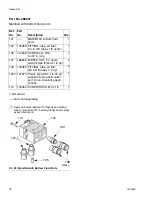
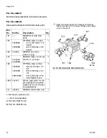
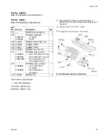
Страница 27: ...fluoroelasto mer 2 12 114134 GASKET polyethylene bottom 1 13 15H317 SCREW mounting manifold M5 4 14 15H318 SCREW SHC 2 15 15H316 GASKET polyethyl ene front 1 16 195222 NUT packing 1 19 192687 PLUG fluid 1 20 114340 RING back up PTFE 1 21 114244 O RING fluoroelasto mer 1 22 192443 GASKET fluid 2 23 See pages 28 29 NOZZLE fluid 0 030 in 1 24 See pages 28 29 CAP air 1 24a 24B546 PIN locating threaded...

Страница 28: ...9041 24A756 HVLP 0 055 1 4 24A689 192453 24A685 288185 289064 24B539 289041 24A757 HVLP 0 070 1 8 24A690 192453 24A685 288185 289065 24B539 289041 24B335 Compliant 0 020 0 5 24B332 192453 24B331 289350 289061 24B540 289042 24A761 Compliant 0 030 0 8 24A687 192453 24A683 288183 289062 24B540 289042 24A762 Compliant 0 042 1 1 24A688 192453 24A684 288184 289063 24B540 289042 24A763 Compliant 0 055 1 ...

Страница 29: ...5 24A695 192453 24A686 N A 289331 24B541 289115 24A777 HVLP 0 070 1 8 24A696 192453 24A686 N A 289332 24B542 289325 24A778 Compliant 0 059 1 5 24A695 192453 24A686 N A 289331 24B538 289050 24A779 Compliant 0 070 1 8 24A696 192453 24A686 N A 289332 24B543 289327 Gun Part Number Spray Type Nozzle Orifice Size in mm Needle Nozzle Kit Includes Items 5 and 23 Item 4 Piston Cap Item 5 Needle Assembly In...

Страница 30: ...long 1 107 166846 NIPPLE SST 1 4 npsm straight pipe thread x 1 4 npt 2 108 120389 FITTING tube air line 3 8 in OD tube x 1 4 npt 2 109 101970 PLUG pipe SST 1 4 18 ptf supplied to plug fluid outlet port in non circulating appli cations 1 114 120453 SCREW SHCS M3 x 18 1 FIG 22 Manifold with Bottom Fluid Ports ti9398c 108 103 101 105 107 Apply anti seize lubricant to threads and mating faces of manif...

Страница 31: ...0389 120537 15D916 FITTING tube air line 3 8 in OD tube x 1 4 npt 8 mm OD tube x 1 4 npt 4 mm OD tube x 1 4 npt shipped loose 1 107 114246 SCREW set 5 16 0 437 in long 1 108 114342 114247 ELBOW male 1 4 18 npt 5JIC x 1 4 18 npt 2 109 101970 PLUG pipe SST 1 4 18 ptf supplied to plug fluid outlet port in non circulat ing applications 1 114 120453 SCREW SCHS M3 x 18 1 FIG 23 Side Fluid Ports and Fan ...

Страница 32: ...pt m 1 105 114246 SCREW set 5 16 0 437 in long 1 107 114342 114247 ELBOW male 1 4 18 npt 5 JIC x 1 4 18 npt 2 108 120389 120537 15D916 FITTING tube air line 3 8 in OD tube x 1 4 npt 8 mm OD tube x 1 4 npt 4 mm OD tube X 1 4 npt shipped loose 2 109 101970 PLUG pipe SST 1 4 18 ptf supplied to plug fluid outlet port in non circulat ing applications 1 114 120453 SCREW SHCS M3 x 18 1 FIG 24 Manifold wi...

Страница 33: ...077 O RING PTFE 2 110 114246 SCREW set hex soc 1 111 120389 120537 15D916 FITTING tube air line 3 8 in OD tube x 1 4 npt 8 mm OD tube x 1 4 npt 4 mm OD tube x 1 4 npt shipped loose 2 112 120388 120538 FITTING tube air inlet 1 4 in OD tube x 1 8 npt m 6 mm OD tube x 1 8 npt m 1 113 103253 SCREW set 2 FIG 25 Manifold with Rear Fluid Ports ti8200a Apply sealant to threads and mating faces of manifold...

Страница 34: ...s bracket and screw Gun Type Application Nozzle Orifice in mm Air Cap without locating pin Nozzle Needle Tip Qty 5 Conventional General Metal 0 086 2 2 289068 289066 289004 Conventional 0 110 2 8 289069 289067 289007 HVLP 0 086 2 2 289070 289066 289004 HVLP 0 110 2 8 289043 289067 289007 Compliant 0 086 2 2 289044 289066 289004 Compliant 0 110 2 8 289045 289067 289007 Conventional Wood 0 020 0 5 2...

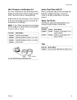
Страница 35: ...er 24B707 Filter is removable without disconnecting the fluid line Includes housing o ring and 0 005 in tip filter equivalent to 100 mesh screen Spray Tip Filters Final filter to prevent foreign particles from ruining sprayed surface smoothness Tips Part No Description 289563 HVLP General Metal 289568 HVLP High Wear 0 059 in 1 5 mm 289569 HVLP High Wear 0 070 in 1 8 mm 289566 HVLP Wood FIG 26 HVLP...

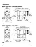
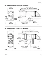
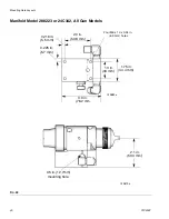
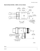
Страница 36: ...4 in 162 6 mm with fluid control knob ti13879a ti13880a 3 9 in 99 1 mm 3 0 in 76 2 mm 1 4 in 35 6 mm 2 8 in 71 1 mm 0 5 in 12 7 mm mounting hole 2 0 in 50 8 mm FIG 28 5 3 in 134 6 mm 6 4 in 162 6 mm with fluid control knob ti13881a ti13882a 1 9 in 48 3 mm 3 7 in 94 0 mm 1 4 in 35 6 mm 2 7 in 68 6 mm 0 5 in 12 7 mm mounting hole 2 0 in 50 8 mm ...

Страница 37: ... in 162 6 mm with fluid control knob ti13883a ti13884a 3 8 in 96 5 mm 3 0 in 76 2 mm 1 4 in 35 6 mm 2 7 in 68 6 mm 0 5 in 12 7 mm mounting hole 2 0 in 50 8 mm FIG 30 5 3 in 134 6 mm 6 4 in 162 6 mm with fluid control knob ti13881a ti13886a 1 8 in 45 7 mm 3 4 in 86 4 mm 1 8 in 45 7 mm 2 7 in 68 6 mm 0 375 in 95 mm mounting hole 2 0 in 50 8 mm ...

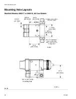
Страница 38: ...18 All Gun Models FIG 31 ti13887a 1 75 in 44 4 mm 1 375 in 34 9 mm 1 5 in 38 1 mm 0 16 in 4 1 mm 0 92 in 23 4 mm 0 4 in 10 2 mm Two M5 x 0 8 x 0 25 in 6 3 mm holes Two 0 13 diameter x 0 31 in 7 8 mm holes Use 1 8 in pin for alignment 0 5 in 12 7 mm mounting hole 2 1 in 53 3 mm ti13879a ...

Страница 39: ... FIG 32 ti13888a 1 75 in 44 4 mm 1 375 in 34 9 mm 2 1 in 53 3 mm 0 18 in 4 6 mm 0 92 in 23 4 mm 0 4 in 10 2 mm Two M5 x 0 8 x 0 25 in 6 3 mm holes Two 0 13 diameter x 0 31 in 7 8 mm holes Use 1 8 in pin for alignment 0 50 in 12 7 mm mounting hole 2 8 in 71 1 mm ti13881a ...

Страница 40: ...fold Model 288223 or 24C342 All Gun Models FIG 33 ti13889a 1 75 in 44 4 mm 1 3 in 33 mm 3 0 in 76 2 mm 0 225 in 5 7 mm 2 0 in 50 8 mm 0 216 in 5 5 mm Four M6 x 1 0 x 0 34 in 6 3 mm holes 0 5 in 12 7mm mounting hole 2 1 in 53 3 mm ti13879a ...

Страница 41: ...Models FIG 34 ti13890a 1 75 in 44 4 mm 1 375 in 34 9 mm 1 1 in 27 9 mm 0 19 in 4 8mm 0 92 in 23 4 mm 0 4 in 10 2 mm Two M5 x 0 8 x 0 25 in 6 3 mm holes Two 0 13 diameter x 0 31 in 7 8 mm holes Use 1 8 in pin for alignment 0 375 in 9 5 mm mounting hole 2 3 in 58 4 mm ti13885a ...

Страница 42: ...ng Hole Layouts 42 313516F FIG 35 Retrofit Adapter Plate 288197 For use with manifold models 288217 288218 288221 288216 and 288211 ti8178a 2 0 in 51 mm 1 4 in 34 9 mm 0 74 in 18 7 mm ti13600a 2 3 in 57 7 mm ...

Страница 43: ...35 and 24A747 24A773 Models 24A774 24A779 Stainless Steel Ultra High Molecular Weight Polyethylene Acetal PTFE PEEK Stainless Steel Ultra High Molecular Weight Polyethylene Acetal PTFE Tungsten Carbide Cylinder Air Pressure psi kPa bar Fluid Pressure psi kPa bar Air Pressure psi kPa bar msec to fully open msec to fully close 50 0 35 3 5 50 0 35 3 5 100 0 7 7 0 58 4 50 4 Conventional Measured at 44...

Страница 44: ...isclose any defect in material or workmanship repairs will be made at a reasonable charge which charges may include the costs of parts labor and transportation THIS WARRANTY IS EXCLUSIVE AND IS IN LIEU OF ANY OTHER WARRANTIES EXPRESS OR IMPLIED INCLUDING BUT NOT LIMITED TO WARRANTY OF MERCHANTABILITY OR WARRANTY OF FITNESS FOR A PARTICULAR PURPOSE Graco s sole obligation and buyer s sole remedy fo...

Отзывы: