


Device Description HG G-71915ZA | English, Revision 01 | Date: 09.09.2021
23
Mounting – Chapter 7
The connections via the inputs X2/X3 are connected in parallel, i.e. there is no input
or output.
If the antenna is connected at the end of the bus:
Mount a CAN terminator.
These terminators can be obtained from various manufacturers and are available in
versions for many sockets and connectors. A terminator for the X2 socket is also of
-
fered by Götting (see 3.1 „Required Accessories“ on page 13).
7.3 Mounting the Transponder Antenna
7.3.1 Operating Conditions of the Antenna
The transponder antenna HG G-71915ZA is approved for indoor and outdoor use. It
may be used in a temperature range from -25 to +50° C. The relative humidity at
25° C may be max. 95 % (without condensation).
The transponder antenna must be mounted firmly on the vehicle so that its position
cannot change during normal operation. Otherwise, the position data will be incor
-
rectly evaluated by the higher-level system and the vehicle may e.g. drive off-track.
No interference signals from clocked motors etc. may be present in the frequency
range 64 ±4 kHz. This also includes interference frequencies that lie on the metal
body of the vehicle.
Eliminate any interfering signals that may be present.
The transponder antenna must be mounted on the vehicle in such a way that the
housing ventilation is not obstructed.
Make sure that the air can circulate unhindered through the housing ventilation.
7.3.2 Minimum Distance Between Antenna and Transponder
The reading distance between the transponder antenna and the transponder is 5 to
60 or 80 mm depending on the transponder type (see Table 47 on page 59).
There must be no metal between the antenna and the transponder.
Non-conductive and non-shielding dirt on the road as well as water, fog, snow and
ice have no influence on the accuracy of the position detection.
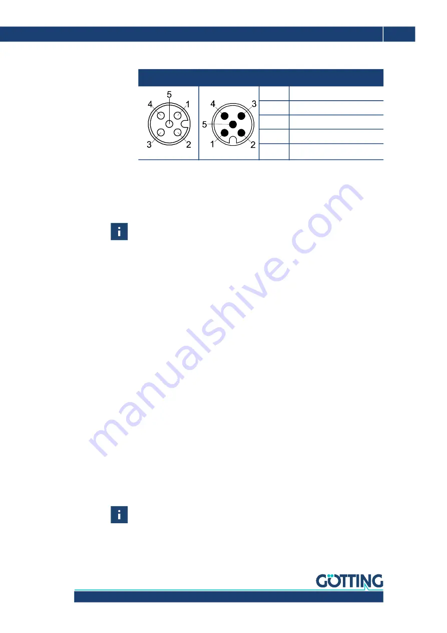
Table 6
CAN-Bus: Pin allocations X2 & X3
X2
X3
Pin
Signal
1
Not connected
2
+Ub (24 V)
3
Ground
4
CAN_H
5
CAN_L
M12, 5-Pin, female
M12, 5-Pin, male


