12
GOSSEN METRAWATT GMBH
6
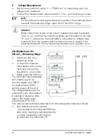
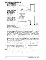
Voltage Measurement
➭
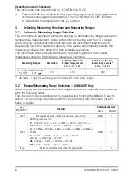
Set the rotary switch to either V
(TRMS) or V
, depending upon the
voltage to be measured.
➭
Connect the measurement cables as shown. The
⊥
jack must be grounded.
Note!
☞
An intermittent acoustic signal warns the operator if the measured value
exceeds the measuring range upper limit in the 600 V range.
Attention!
!
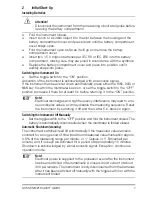
Make certain that neither of the current measuring ranges is selected
(“mA” or “A”) and that the measuring cables are connected to the right
“V” und “^” jacks when the multimeter is connected for voltage mea-
surement! Both the operator and the instrument are in danger if the
breaking thresholds for the fuses are exceeded due to operator error!
Zero Balancing in the
300 mV
Measuring Range
➭
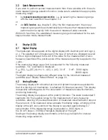
Select the 300 mV
measuring range.
➭
Connect the measure-
ment cables to the instru-
ment and connect the
free ends to one another.
➭
Briefly press the
FUNC
key.
The instrument acknowledges
zero balancing with an
acoustic signal, and “
000
.
0
”
(
±
1 digit) and the ZERO
symbol appear at the LCD.
The voltage displayed at the
moment the key was pressed
is used as a reference value
(max.
±
20 0 digits which
corresponds to 20 mV).
This value is automatically subtracted from all subsequently measured values.
➭
Zero balancing can be cleared:
– by pressing and holding the
FUNC
key,
after which clearing is acknowledged by
– a twice repeated acoustic signal,
by switching the instrument off.
– (+)
~
+ (–)
~


