


12
GMC-I Messtechnik GmbH
8
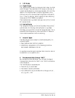
Voltage Measurement
➭
Turn the selector switch, depending upon the desired
input resistance, to V
(R
E
> 10 M
)
or V
400k
(R
E
= 400 k
).
Note!
The measuring instrument is provided with the
switch position V
400k
for electricians, which has
an input resistance of approx. 400 k
. This
reduces incorrect message displays due to
capacitive interference during voltage measure-
ments in power supply networks to a minimum.
➭
Connect the measurement cable as shown. Connector
jack “
” should be grounded, and the second measuring
cable with a higher potential connected to jack “V”.
Note!
The measuring rage 400 mV
can only be
selected manually with the “AUTO/MAN” key!
Attention!
Make certain that the
current ranges
(“mA” or
“A”)
are deactivated and that the measurement
cables are connected to the correct jacks, “V
and
”
, before connecting your multimeter for
the measurement of voltage! If the fuse tripping
limit values are exceeded due to operator error,
both the operator and the instrument are in dan-
ger! Observe the voltage limit values as printed
on the instrument!
➭
Select the respective voltage type which corresponds to
the measuring magnitude by briefly pressing the multi-
function key. Each activation of the key causes alternate
switching between DC and AC, as well as aknowledge-
ment by means of an acoustic signal. The symbols
DC
and
AC indicate the selected voltage type in the LCD
display.
After selection of this function with the selector switch, the
voltage type AC is always activated
mA
600V
A
V
F
600 V CAT II / 300 V CAT I I I
400mA fused
10A fused