


GHS SERIES
OM-05450
PAGE B-5
INSTALLATION
When handling very hot or cold liquids, install a
pressure relief valve in any part of the system that
can be valved off or isolated; this will protect piping
against damage from liquid thermal expansion or
contraction from temperature changes during
shutdown.
Barrier Liquids for 65E Cartridge Triple Lipseal
In general, a barrier liquid is
always
recommended
for these seals. This requirement may be satisfied
by a simple grease zerk, or it may become more
complicated based on the application. The follow
ing barrier liquid guidelines are offered for maxi
mum performance;
1.
Select a clean, lubricating liquid that is
compatible with the pump construction
(iron or 316 SST).
2.
Select a clean, lubricating liquid that is
compatible with the pumped product
and with the pump construction (iron or
316 SST).
3.
Depending upon pump shaft speed, a
pressurized barrier liquid may not be re
quired. Consult the factory for your spe
cific application.
Barrier Liquids for Dual Mechanical Seals
Pumps equipped with dual (tandem) mechanical
seals require a barrier liquid to prevent contamina
tion of the seal assembly by the liquid being
pumped. The barrier liquid must have the following
characteristics:
a. The barrier liquid must have sufficient lubricat
ing characteristics, including an optimum vis
cosity of 1 to 5 cSt at the temperature of the
liquid being pumped.
b. The barrier liquid must be compatible in all re
spects with all pump and seal components to
which it will be exposed.
c. The barrier liquid must be compatible in all re
spects with the liquid being pumped.
Pumps equipped with dual mechanical seals re
quire the barrier liquid to be supplied at a continu
ous pressure equivalent to the maximum dis
charge pressure in order to avoid inboard seal face
separation. The maximum barrier liquid pressure
that can be applied depends primarily on the maxi
mum seal design pressure (consult the factory).
Do not
pressurize tandem seals. Pressurizing a
tandem seal will cause the seal faces to separate,
resulting in leakage and/or damage to the seal.
Refer to the appropriate section in
Seal Appendix,
Section F
for your specific seal option for operating
instructions for the barrier liquid reservoir kit.
ALIGNMENT
Make certain that power to the drive unit
is disconnected before attempting to
connect the pump drive; otherwise, per
sonal injury may result.
NOTE
See
ROTATION
in Section C before mounting the
pump on the base.
Coupled Drives
When using couplings, the axis of the power
source must be aligned to the axis of the pump
shaft in both the horizontal and vertical planes.
Most couplings require a specific gap or clearance
between the driving and the driven shafts. Refer to
the coupling manufacturer's service literature.
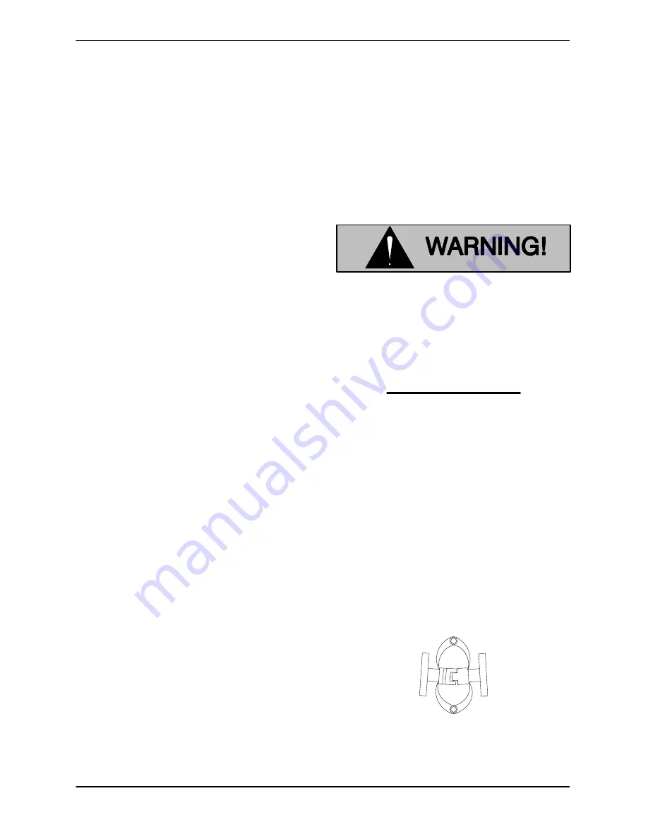
Align spider insert type couplings by using calipers
to measure the dimensions on the circumference
of the outer ends of the coupling hub every 90
.
The coupling is in alignment when the hub ends
are the same distance apart at all points (see Fig
ure B‐2).
Figure B‐2.
Spider‐type Couplings
Align non‐spider type couplings by using a feeler
gauge or taper gauge between the coupling halves


