


GHS SERIES
OM-05450
PAGE B-4
INSTALLATION
easier because the pump will not have to remove
as much air in the line.
D
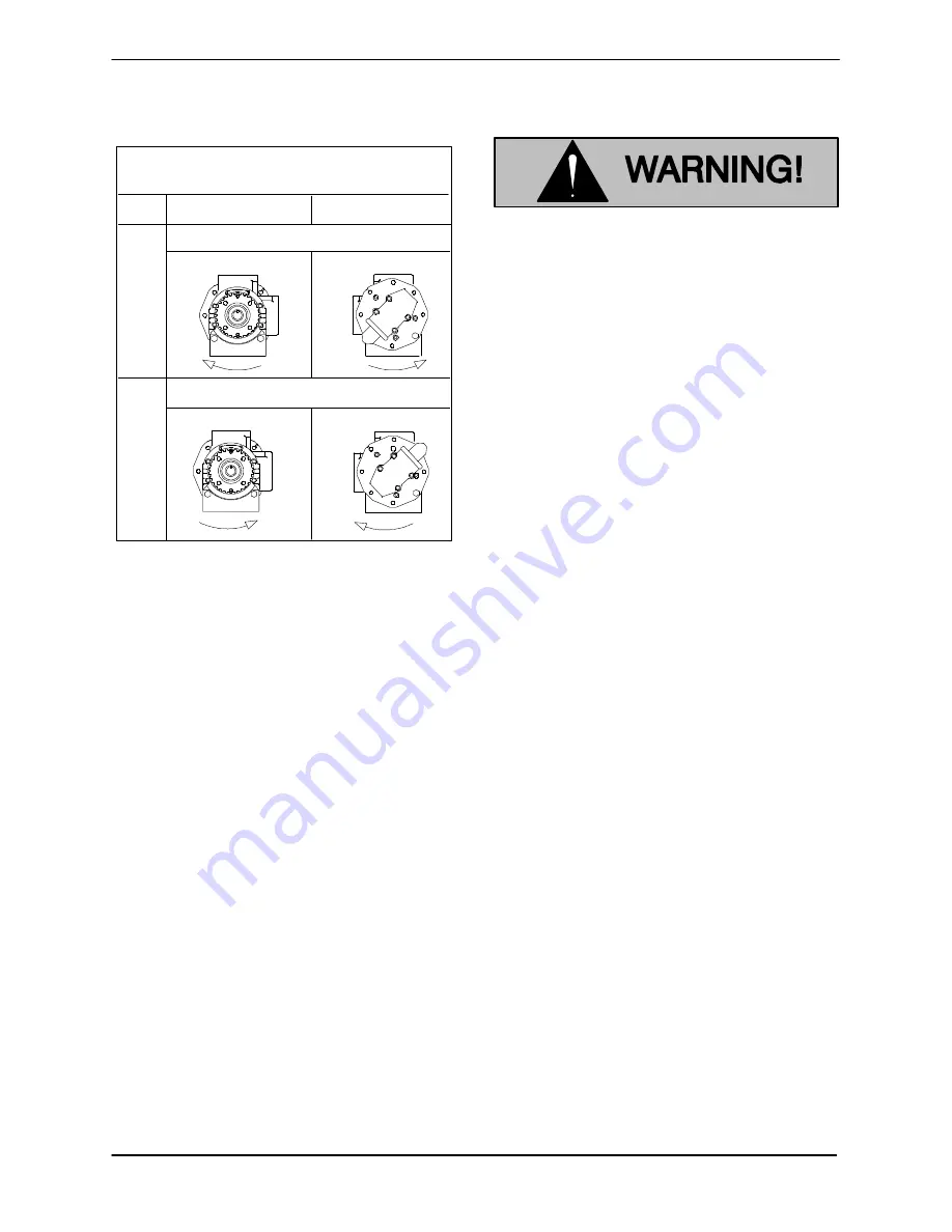
Housing Position For Std. 90
Pump
(3‐12 O'clock) Head Mounted Relief Valve
STD.
OPT.
Rotation Clockwise
Drive End
Front End
Rotation Counter‐clockwise
01A
D
S
S
S
D
D
S
Figure B‐1. Typical Port Positions & Rotation
The discharge and suction lines must be inde
pendently supported to avoid vibration and strain
on the pump. For maximum pumping capacity,
keep the lines as short and straight as possible. El
bows and fittings used in the lines increase friction
losses; minimize their use. Reducers used in suc
tion lines should be the eccentric type installed
with the flat part uppermost to avoid creating air
pockets.
Before tightening a connection or flange, align it
exactly with the pump port. Never pull a pipe line
into place by tightening the flange bolts and/or
couplings.
Temperature Control
If your pump is equipped with temperature control
jacket(s), follow the same guidelines described for
suction and discharge piping installation when
installing the temperature control piping. Be sure
to install a shutoff valve in each supply line to the
jacket(s) for serviceability.
To assist with air removal within the system and to
improve heat transfer efficiency, it is recommen
ded that the jacket be plumbed with the incoming
liquid entering the bottom of the jacket and exiting
the top.
Liquid used for temperature control
must not exceed 600
_
F (316
_
C) or 150
psi (1034 kPa) pressure. Higher temper
atures or pressures can result in dam
age to the equipment and/or serious in
jury to personnel.
Gauges
Install a vacuum gauge in the suction line and a dis
charge pressure gauge in the discharge line (both
should be as close as possible to the pump) to
monitor operation and assist in troubleshooting.
Strainers
Because of the close‐tolerance moving parts of
this pump, it is recommended that a strainer be in
stalled in the suction line. The strainer should be
large enough to prevent excessive vacuum, and
capable of operating under high vacuum without
collapsing. The net open area of the strainer
screen depends on liquid viscosity and desired
flow rate; in any case, the sum of the area of all the
holes in the screen should be three to five times the
area of the suction pipe.
Sealing
Even a slight leak will affect priming, head, and ca
pacity, especially in a suction lift application. Seal
all piping joints, valves and gauges with pipe dope
or teflon tape. The sealing material should be com
patible with the liquid being pumped.
Valves
To avoid air pockets, install piping valves with the
stem horizontal.
To prevent leakage during shutdown, install a shut
off valve in the discharge line, particularly on a
flooded suction application. Shutoff valves are not
recommended for suction lines.
It is
not
recommended that a foot valve be installed
at the end of the suction line. If desired to install a
foot valve, consult the factory.


