


OM-06100
S SERIES PUMPS
PAGE B - 6
INSTALLATION
b.
Driven Electrode:
A rod or pipe, 3/4 inch
(19,1 mm) in diameter minimum, 8 feet (2,4 m)
long, completely driven into the ground.
c.
Buried electrode:
If rock or stone prevents
embedding the full 8 foot (2,4 m) length of the
ground rod, bury it horizontally in a trench.
Space the ground rod or plates at least 6 feet
(1,8) from any other electrode or ground rod,
such as those used for signal circuits, radio
grounds, lightning rods, etc.
The earth surrounding the ground rod or plate
must
contain enough moisture to make a
good electrical connection. In dry or sandy
areas, pour water around the rod, or consult
qualified personnel to devise a method of im
proving the connections.
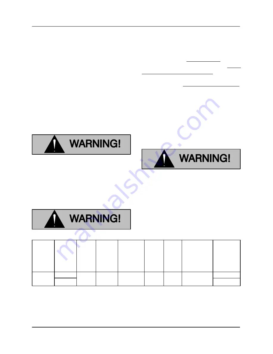
The electrical power used to operate
this pump is high enough to cause inju
ry or death. Make certain that the control
box is properly grounded after installa
tion.
Refer to the literature accompanying the control
box for field wiring connections.
Pump Power Cable Connections
The electrical power used to operate
this pump is high enough to cause inju
ry or death. Obtain the services of a
qualified electrician to make all electri
cal connections. Make certain that in
coming power to the control box is in the
OFF position and locked out, or that the
power supply to the control box has
been otherwise cut off and locked out,
before connecting power or accessory
cables.
The pump is provided with a 50 ft. (15,2 m) power
cable (see Table B-4 for standard power cable
specifications). If a longer cable is required, an op
tional cable assembly
must
be ordered from the
factory. Splicing of the power cable is
not
recom
mended by the Gorman‐Rupp Company due to
safety and warranty considerations.
Never attempt to alter the length or re
pair any power cable with a splice. The
pump motor and cable must be com
pletely waterproof. Injury or death may
result from alternations.
Table B‐4. Pump Power Cable Specifications
Pump
Model
Voltage/
Phase
A.W.G
Cable
Size
Conductor
Dia.
Inches
(mm)
DC
Resistance
(ohms) at
25
C (77
F)
per 1000 ft.
(305 m)
Cable
O.D.
Inches
(mm)
Amp
Rating
(See
Note
Below)
Cable
Type
NOTE: *
Amp Rating at 30
C (86
F)
Canada Use Type SOW Cable
** Amp Rating at 40
C (104
F)
Voltage
Drop
per 100 ft.
(30,5m) at
Max. Load
6
1.01 (26)
0.21 (5)
79**
GGC
0.45
3.96
3.15
460/3
575/3
S6C
When necessary to change or connect the pump
power cable to the control box, make certain the in
coming power is
OFF
and
LOCKED OUT
, Make
certain the control box is
PROPERLY GROUNDED
and that the electrical data on the control matches
the motor name plate data.


