179732
Instructions for use, installation and connection
15
the cabinet of equal height as the appliance. Suspended
cabinets may be installed at such height as not to impede the
cooking process.
Minimum vertical distance from the appliance must be at
least 650 mm.
•
In case the gas specifications do not correspond to the
requirements of the appliance, call the service center or
the gas supplier. Qualified technician will make
necessary amendments to agree with your type of gas.
•
Any other amendments or replacements requiring tools, may
be performed by qualified personnel only.
•
In any case, you are allowed to replace only such parts
which do not require any tools for their replacement!
•
Panels, glue and furniture lining from artificial materials,
adjacent to the appliance must be temperature resistant
(>90°C), otherwise they might be deformed.
•
Mains lead behind the cooker must be placed in such
manner to avoid touching the back panel of the cooker
because of the heat it develops during operation.
•
Remove any packaging materials (foils, artificial foam, nails,
etc.) from the reach of children, because they represent
potential danger. Children may swallow small parts, or
suffocate with foils.
Leveling the appliance and extra support
(certain models only)
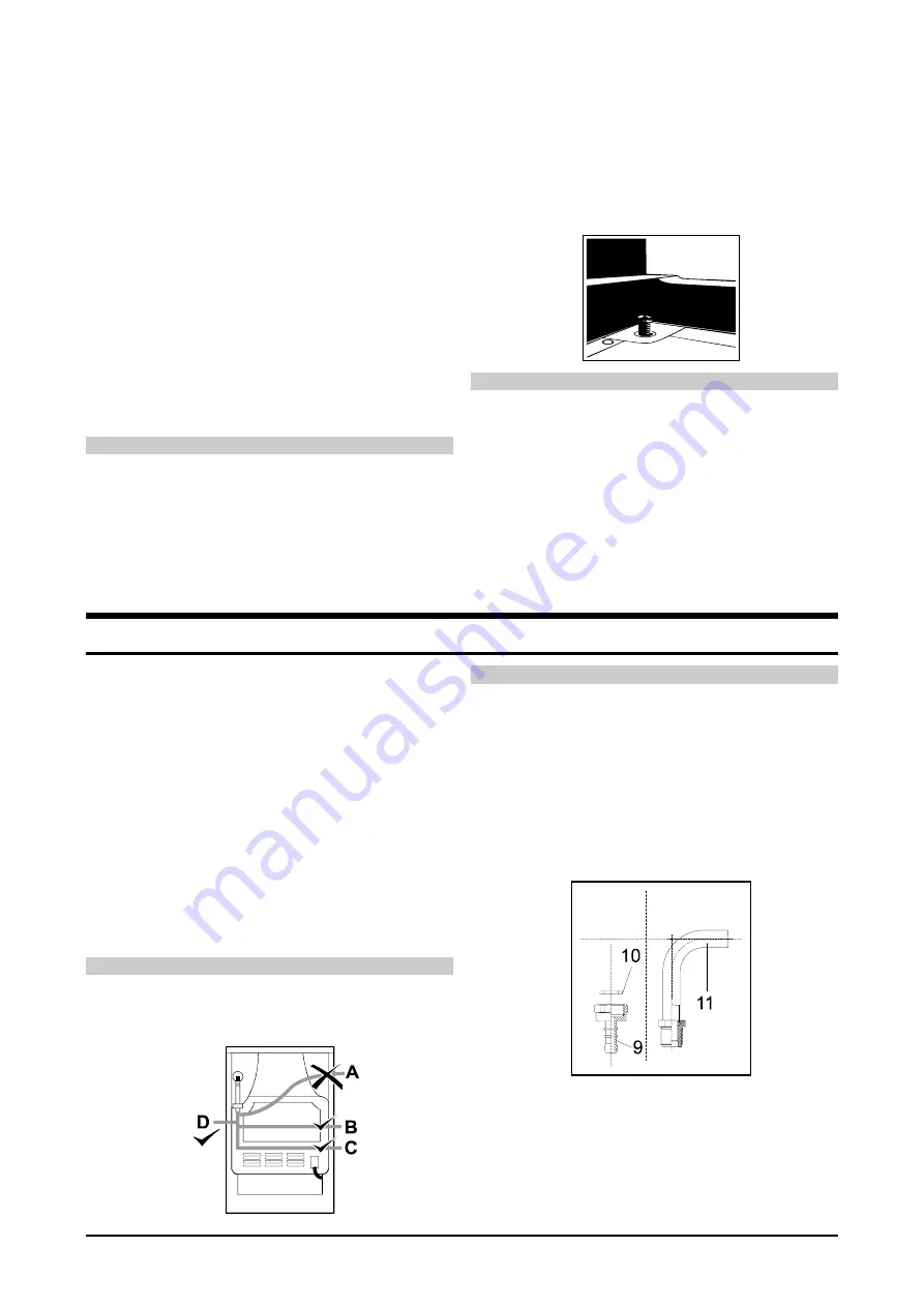
Your appliance is equipped with extra support. The height of
the cooker with the support is 90 cm, and without support it is
85 cm. Left and right side of the support is equipped with two
wheels to facilitate relocation. In the front part, on both sides
there are two adjustable screws, used to level the cooker and
adjust its upper edge in line with the adjacent kitchen furniture.
Adjustable legs are accessible when the drawer is pulled out.
Adjust the position of the cooker by turning the legs in one
direction or another. Adjustable legs will be turned easier if the
appliance is somewhat lifted up and tilted.
Additional support may be removed by unscrewing the four
screws holding it to the bottom of the cooker. In such case
relocate the adjustable screws from the support and place
them left and right at the bottom front base of the cooker. Level
the cooker as described earlier.
Some cookers are equipped with four adjusting screws (two in
front and two at the back), used for leveling the appliance or
adjusting its heights to match the adjacent furniture.
Manufacturer's adjustments
Gas cookers are tested and equipped with the symbol CE.
Gas cookers are supplied sealed and adjusted to natural gas H
or E (20 mbar) or to liquid gas (50 or 30 mbar). Specifications
are indicated on the rating plate, located in the interior of the
oven and accessible when the oven door is opened.
Gas load and consumption of particular burners are indicated
in the table below.
Modification to another type of gas requires the exchange of
gas nozzles. Information are indicated in the table below.
In case of damage or broken seal the functional components of
the cooker must be rechecked and resealed in accordance with
the instructions for installation.
Such functional components are: fixed nozzle for large flame
and adjustable nozzle for small flame.
Gas connections
•
Connect the appliance in accordance with the regulations of
the local gas supplier.
•
Gas cooker is equipped with the gas connection on the right
side with the exterior thread ISO 7-R1/2.
•
Certain appliances are supplied with the attached liquid gas
coupling and the sealing gasket.
•
The connection R1/2 must be gripped tight during the
connection procedure to prevent it from revolving.
•
For sealing use only approved gaskets.
•
The deformation of the non-metal gasket connection
thickness during tightening may not exceed 25%.
•
Connect the appliance to the gas coupling by means of
certified flexible hose. The hose may not touch the bottom
panel of the appliance or the rear panel and ceiling of the
oven.
•
Connect the appliance in accordance with the regulations of
the local gas supplier.
Important
! Check all the connections for tightness after the
installation!
Flexible hose connection
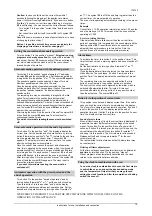
In case the appliance is connected by means of a flexible
hose, the position A of the hose is not permissible.
In case the connection hose is made of metal, position A is
permissible.
Beginning of operation
Start using the appliance in accordance with the instructions
for use.
Lit up all burners and check the stability of the flame with high
and low setting. Adjust air intake if necessary.
After that, take time and explain the operation and control of
the appliance to the user and read with him the instructions for
use.
Liquefield gas connection
9
Pipe coupling liquefied
10
Gasket (certain models only)
11
Connection R1/2


