© Gooligum Electronics 2015
www.gooligum.com.au
Baseline and mid-range PIC training and dev board operation guide
Page 30
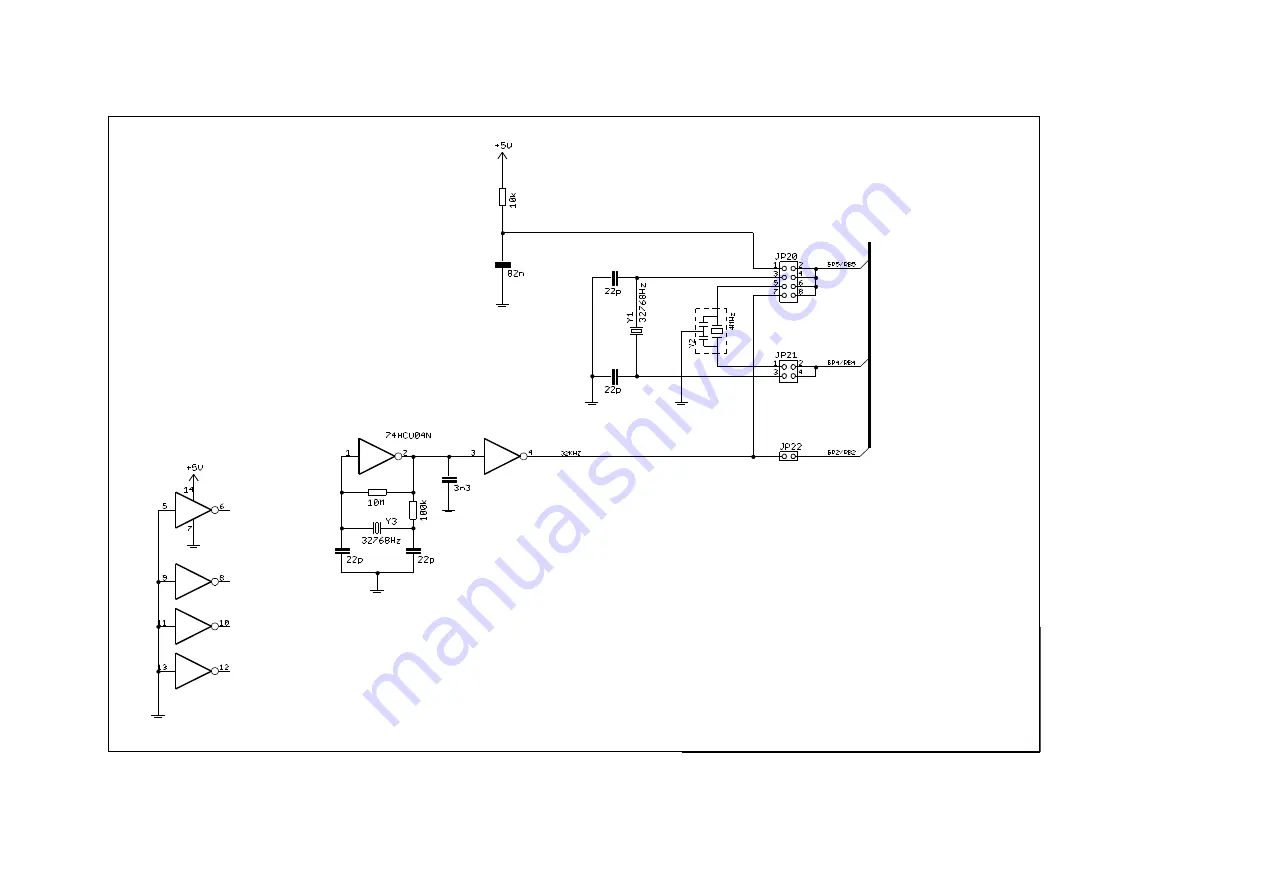
Sheet 3: Oscillator section
Страница 1: ...sy to follow the Gooligum baseline mid range and introductory enhanced mid range lessons It works with a PICkit 2 or PICkit 3 programmer and supports all 8 and 14 pin baseline mid range and enhanced m...
Страница 2: ...an continue to use the board for PIC development Construction If your training board came fully assembled you can ignore this section The training board kit consists of a printed circuit board a set o...
Страница 3: ...verlay shows BC337 BC547 or BC548 transistors may have been supplied with your kit That s ok they ll all work fine in this application driving the 7 segment displays and have the same pin out Whicheve...
Страница 4: ...et U2 marked 16F is for 14 pin PIC16F devices Note you must plug a PIC into ONLY ONE socket at once If you ve been using a PIC10F and want to use a PIC12F or PIC16F remove the PIC10F from the 10F sock...
Страница 5: ...all 14 pin PICs so the LED on that pin is labelled simply RC3 LEDs are available on all output pins except RC4 and RC5 To enable connect an LED simply close its associated jumper Pushbutton switches...
Страница 6: ...very position in jumper block JP4 That is you use six shunts at once in JP4 Connect segment E to either RA RB2 or RA RB4 by placing a shunt in one of the two positions in jumper block JP5 selecting th...
Страница 7: ...he piezo can be driven at higher volume by a double ended or half bridge PWM output by placing a shunt across positions 2 and 3 of JP23 connecting its other side to PWM output P1B Finally every PIC pi...
Страница 8: ...E JP6 1 2 Connects common cathode of LED digit 1 to ground 2 3 Connects common cathode of LED digit 1 to transistor controlled by RC5 JP7 Enables external pull up resistor on GP2 RA2 RB2 JP8 Connects...
Страница 9: ...side connects to P1A 2 3 Connects one side of piezo sounder to P1B other side connects to P1A JP24 1 2 Connects 10 k potentiometer to RA0 CIN C1IN 2 3 Connects LDR1 to AN0 CIN C1IN JP25 1 Connects LD...
Страница 10: ...uld place shunts across all six jumpers numbered 1 6 in the block Where a table cell is blank the jumper should be left open In many cases it won t matter if additional jumpers are connected but to en...
Страница 11: ...LED GP RA2 LED GP RA4 LED GP RA5 LED RC0 LED RC1 LED RC2 LED RC3 LED Clock source Crystal 32 kHz T0CKI Piezo AN0 source LDR2 Var Freq digital Var Freq analog Lesson Example 3 4 5 6 7 8 9 10 11 12 13...
Страница 12: ...0 digit 3 GP RA0 LED GP RA1 LED GP RA2 LED GP RA4 LED GP RA5 LED RC0 LED RC1 LED RC2 LED RC3 LED Clock source Crystal 32 kHz T0CKI Piezo AN0 source LDR2 Var Freq digital Var Freq analog Lesson Example...
Страница 13: ...thode GP RA2 pull up RC5 digit 1 RA5 digit 2 RC0 digit 3 GP RA0 LED GP RA1 LED GP RA2 LED GP RA4 LED GP RA5 LED RC0 LED RC1 LED RC2 LED RC3 LED Clock source Crystal 32 kHz T0CKI Piezo AN0 source LDR2...
Страница 14: ...D RC2 LED RC3 LED Clock source Crystal 32 kHz T0CKI Piezo AN0 source LDR2 Var Freq digital Var Freq analog Lesson Example 3 4 5 6 7 8 9 10 11 12 13 14 15 16 17 18 19 20 21 22 23 24 25 26 27 9 1a 1 2 1...
Страница 15: ...E digit 1 cathode GP RA2 pull up RC5 digit 1 RA5 digit 2 RC0 digit 3 GP RA0 LED GP RA1 LED GP RA2 LED GP RA4 LED GP RA5 LED RC0 LED RC1 LED RC2 LED RC3 LED Clock source Crystal 32 kHz T0CKI Piezo AN0...
Страница 16: ...digit 1 RA5 digit 2 RC0 digit 3 GP RA0 LED GP RA1 LED GP RA2 LED GP RA4 LED GP RA5 LED RC0 LED RC1 LED RC2 LED RC3 LED Clock source Crystal 32 kHz T0CKI Piezo AN0 source LDR2 Var Freq digital Var Freq...
Страница 17: ...LED RC2 LED RC3 LED Clock source Crystal 32 kHz T0CKI Piezo AN0 source LDR2 Var Freq digital Var Freq analog Lesson Example 3 4 5 6 7 8 9 10 11 12 13 14 15 16 17 18 19 20 21 22 23 24 25 26 27 7 1 all...
Страница 18: ...ED GP RA1 LED GP RA2 LED GP RA4 LED GP RA5 LED RC0 LED RC1 LED RC2 LED RC3 LED Clock source Crystal 32 kHz T0CKI Piezo AN0 source LDR2 Var Freq digital Var Freq analog Lesson Example 3 4 5 6 7 8 9 10...
Страница 19: ...git 3 GP RA0 LED GP RA1 LED GP RA2 LED GP RA4 LED GP RA5 LED RC0 LED RC1 LED RC2 LED RC3 LED Clock source Crystal 32 kHz T0CKI Piezo AN0 source LDR2 Var Freq digital Var Freq analog Lesson Example 3 4...
Страница 20: ...C5 digit 1 RA5 digit 2 RC0 digit 3 GP RA0 LED GP RA1 LED GP RA2 LED GP RA4 LED GP RA5 LED RC0 LED RC1 LED RC2 LED RC3 LED Clock source Crystal 32 kHz T0CKI Piezo AN0 source LDR2 Var Freq digital Var F...
Страница 21: ...LED RC3 LED Clock source Crystal 32 kHz T0CKI Piezo AN0 source LDR2 Var Freq digital Var Freq analog Lesson Example 3 4 5 6 7 8 9 10 11 12 13 14 15 16 17 18 19 20 21 22 23 24 25 26 27 11 1 3 2 3 3 4...
Страница 22: ...A5 digit 2 RC0 digit 3 GP RA0 LED GP RA1 LED GP RA2 LED GP RA4 LED GP RA5 LED RC0 LED RC1 LED RC2 LED RC3 LED Clock source Crystal 32 kHz T0CKI Piezo AN0 source LDR2 Var Freq digital Var Freq analog L...
Страница 23: ...ED GP RA5 LED RC0 LED RC1 LED RC2 LED RC3 LED Clock source Crystal 32 kHz T0CKI Piezo AN0 source LDR2 Var Freq digital Var Freq analog Lesson Example 3 4 5 6 7 8 9 10 11 12 13 14 15 16 17 18 19 20 21...
Страница 24: ...10 k 5 1 4W resistors 2 22 k 5 1 4W resistors 1 100 k 5 1 4W resistor 1 10 M 5 1 4W resistor 1 10 k trimpot with thumbwheel e g Bourns 3352T 1 100 k trimpot with thumbwheel e g Bourns 3352T 3 BC337 NP...
Страница 25: ...r snap into 16 1 2 headers 1 1 9 pin 0 1 snappable header snap into 3 1 3 headers 1 2 19 pin 0 1 snappable header snap into 1 2 3 1 2 4 1 2 6 and 3 2 2 headers 1 13 mm PCB ext drive piezo sounder e g...
Страница 26: ...509 I P MCU 1 PIC12F629 I P MCU 1 PIC12F1501 I P MCU 1 PIC16F506 I P MCU 1 PIC16F684 I P MCU 1 PIC16F1824 I P MCU 1 1 nF ceramic capacitor 1 100 nF ceramic capacitor 2 1 F ceramic capacitor 1 100 5 1...
Страница 27: ...motor control examples optional Qty Description 2 PSMN022 30PL or similar N channel logic level MOSFETs 2 NDP6020P or similar P channel logic level MOSFETs 1 SN754410 or L293D quad half H driver with...
Страница 28: ...Gooligum Electronics 2015 www gooligum com au Baseline and mid range PIC training and dev board operation guide Page 28 Appendix C Schematics Sheet 1 Main...
Страница 29: ...Gooligum Electronics 2015 www gooligum com au Baseline and mid range PIC training and dev board operation guide Page 29 Sheet 2 Digital I O...
Страница 30: ...Gooligum Electronics 2015 www gooligum com au Baseline and mid range PIC training and dev board operation guide Page 30 Sheet 3 Oscillator section...
Страница 31: ...Gooligum Electronics 2015 www gooligum com au Baseline and mid range PIC training and dev board operation guide Page 31 Sheet 4 Analog...