Hardware
basicCAN 61 PLUS – User Manual
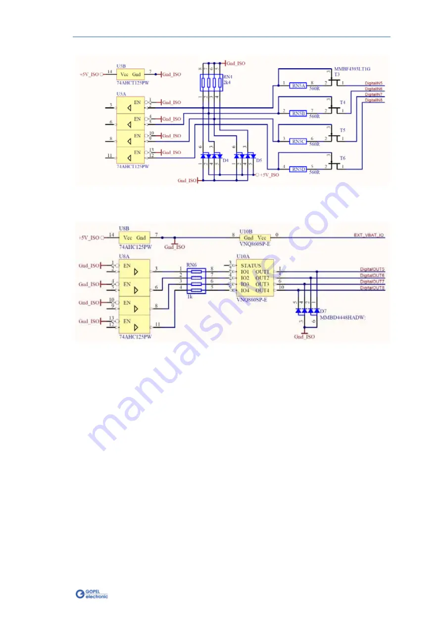
3-15
Figure 3-12: Circuit diagram extract of Digital inputs 5..8 for IO Extension board Type 2
Figure 3-13: Circuit diagram extract of Digital outputs 5..8 for IO Extension board Type 2
Страница 1: ...EL electronic GmbH Goeschwitzer Str 58 60 D 07745 Jena 49 3641 6896 597 ats_support goepel com www goepel com basicCAN 61 PLUS USB Controller User Manual Translation of Original docu Document Version...
Страница 2: ...prior notice due to technical progress In case of inaccuracies or errors appearing in this manual GOEPEL electronic GmbH assumes no liability or responsibility Without the prior written permission of...
Страница 3: ...3 2 2 Basic Characteristics 3 2 3 3 FRONT VIEW 3 3 3 4 REAR VIEW 3 4 3 5 FUNCTION 3 4 3 5 1 Status LEDs 3 4 3 5 2 Supply of basicCAN 61 PLUS 3 5 3 5 3 Test object Supply 3 5 3 5 4 OnBoard Interfaces...
Страница 4: ......
Страница 5: ...laration of Conformity we declare the compliance of the GOEPEL electronic GmbH product described in this Manual with the requirements of the Directive 2006 95 EG Low Voltage Directive and with the Dir...
Страница 6: ......
Страница 7: ...ed CD and follow the instructions Your basicCAN 61 PLUS can be operated under Windows XP as well as under Windows 7 32 bit and Windows 7 64 bit Before connecting the basicCAN 61 PLUS stand alone hardw...
Страница 8: ...perly embedded by the system As an example the following figure shows the successful embedding of four basicCAN 61 PLUS devices each device appears as USB 6153 in the Device Manager Please note that t...
Страница 9: ...driver installation required After the Hardware Installation the device can directly be addressed via the IP Address see also Addressing This IP Address can be changed by the HardwareExplorer The newl...
Страница 10: ......
Страница 11: ...r K Line interfaces onboard see OnBoard Interfaces optionally 2 FlexRay nodes with 2 channels each see FlexRay Extension board 4 digital input and output channels with TTL level onboard see Digital IO...
Страница 12: ...x 82 mm L x W x H A basicCAN 61 PLUS has the following basic characteristics Indication Min Typ Max Unit Remarks CAN LIN or K Line interfaces 2 4 See OnBoard Interfaces CAN Extension 2 See OnBoard In...
Страница 13: ...us LEDs 1 4 DO 1 2 3 4 State of Digital outputs 1 4 Power 1 2 3 Power LEDs Node 1 CAN 1 Node 2 CAN 2 Node 3 CAN 3 optionally also LIN or K Line possible Node 4 CAN 4 optionally also LIN or K Line poss...
Страница 14: ...basicCAN 61 PLUS The operation states are explained in the following table LED 1 LED 2 LED 3 LED 4 Remarks Permanently ON Controller does not run error Alternately blinking Bootloader software runs bl...
Страница 15: ...with coaxial power plug 2 1 x 5 5 mm plus polarity inside To supply the test object a voltage connected to the ext Power Front connection at the device s rear side is distributed to the KL30 KL15 KL31...
Страница 16: ...ation In the case of further inquiries please contact our support department ats_support goepel com The position and orientation of the transceivers can be seen in the following figure Each transceive...
Страница 17: ...lation Isolated power supply of the transceivers The following table shows the main characteristics of a FlexRay module Symbol Indication Min Typ Max Unit Remarks FlexRay interface Transmission rate 2...
Страница 18: ...6 optionally Transmission rate 1 Mbit s UBATint Internal battery voltage 12 V RCAN Termination high speed transceiver 120 detachable LIN V2 1 Interfaces Node 3 4 optionally Transmission rate 19 2 kbit...
Страница 19: ...ng parameters Symbol Indication Min Typ Max Unit Remarks Digital inputs 1 4 onboard UIH High level input voltage 3 5 5 5 V UIL Low level input voltage 1 5 V IL Input leakage current 35 A Digital outpu...
Страница 20: ...Hardware 3 10 basicCAN 61 PLUS User Manual Figure 3 6 Circuit diagram extract of onboard Digital Inputs 1 4 Figure 3 7 Circuit diagram extract of onboard Digital outputs 1 4...
Страница 21: ...lows Symbol Indication Min Typ Max Unit Remarks Digital inputs 5 8 N Number of inputs 4 UIH High level input voltage 3 5 25 V UIL Low level input voltage 3 0 V IL Input current 1 8 mA Digital outputs...
Страница 22: ...3 12 basicCAN 61 PLUS User Manual Figure 3 8 Circuit diagram extract of Digital inputs 5 8 for IO Extension board Type 1 Figure 3 9 Circuit diagram extract of Digital outputs 5 8 for IO Extension boar...
Страница 23: ...basicCAN 61 PLUS User Manual 3 13 Figure 3 10 Circuit diagram extract of Analog inputs 1 6 for IO Extension board Type 1 Figure 3 11 Circuit diagram extract of Analog outputs 1 6 for IO Extension boar...
Страница 24: ...al outputs 5 8 N Number of outputs 4 UOH High level output voltage 25 V Supply via pin UEXTIO UOL Low level output voltage open V Integrated recovery diode IOUT Output current 200 mA Analog inputs N N...
Страница 25: ...asicCAN 61 PLUS User Manual 3 15 Figure 3 12 Circuit diagram extract of Digital inputs 5 8 for IO Extension board Type 2 Figure 3 13 Circuit diagram extract of Digital outputs 5 8 for IO Extension boa...
Страница 26: ...3 16 basicCAN 61 PLUS User Manual Figure 3 14 Circuit diagram extract of Analog inputs 1 4 for IO Extension board Type 2 Figure 3 15 Circuit diagram extract of Analog outputs 1 4 for IO Extension boar...
Страница 27: ...interface takes place exclusively according to their serial numbers The device with the least serial number is always the device with the number 1 To improve clarity we recommend to connect several b...
Страница 28: ...table shows the pinout of the LIN frontal connectors Node 3 4 optionally assigned type D SUB 9poles female Pin Signal Pin Signal 1 Not used 6 Not used 2 Not used 7 LIN 3 GNDISO 8 Not used 4 Not used...
Страница 29: ...ly assigned type D SUB 15poles female Pin Signal Pin Signal 1 ANALOG_IN1 9 ANALOG_IN2 2 ANALOG_IN3 10 ANALOG_IN4 3 ANALOG_IN5 11 ANALOG_IN6 4 GNDISO 12 ANALOG_OUT1 5 ANALOG_OUT2 13 ANALOG_OUT3 6 ANALO...
Страница 30: ...xtension is not mounted is indicated by bold characters The following table shows the pinout of the Digital frontal connector for IO Extension Type2 partly optionally assigned type D SUB 25poles femal...
Страница 31: ...ional K Line node for basicCAN 61 PLUS devices onboard to upgrade on 3 or 4 communication nodes incl transceiver module s Note The total quantity of installable CAN LIN K Line nodes at the same time a...
Страница 32: ...c software DIAG J1939 J1939 on board CAN Diagnostic software CAL CCP2 1 CAN Calibration Protocol CCP2 1 LIN adv lib Advanced library for Test of the LIN protocol specific 2 0 2 1 Net2Run Software tool...
Страница 33: ...Software basicCAN 61 PLUS User Manual 4 1 4 Software There are the following ways to integrate basicCAN 61 PLUS hardware in your own applications G API Programming UserCode Programming...
Страница 34: ...blocking execution for pending firmware commands The command acknowledgement is provided via a callback mechanism With the HardwareExplorer see also Ethernet GOEPEL electronic provides an effective ha...
Страница 35: ...e virtual memory space which ensures safe test execution and improves reliability The UserCode run time module uses a superset of the G API commands for Windows ensuring an easy migration of existing...
Страница 36: ...ow shows the Net2RunIDE development system Figure 4 1 Net2Run IDE Window Please consult the G API documentation for further information This documentation and the installation software are located in...
Страница 37: ...N Interfaces 3 6 Computer interfaces 3 17 D Digital IO 3 9 Driver Installation USB 2 3 E Ethernet 2 5 3 17 Extension FlexRay 3 7 IO 3 11 F FlexRay extension 3 7 G G API 4 2 H HardwareExplorer 2 5 4 2...